
Ducted Electric Propulsion for Manned & Cargo eVTOLs
Distributed 400V–800V DC electric ducted fan powertrains delivering 53 dB(A) vertiport compliance, fail-safe OEI redundancy, and flight-proven aerodynamic integration for global aircraft developers.
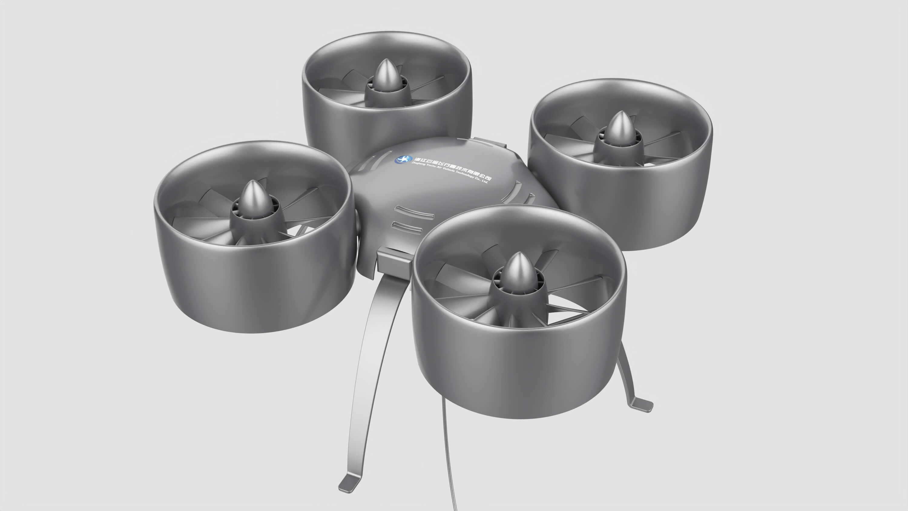
An eVTOL propulsion system requires balanced performance across two opposing flight regimes: maximum static thrust during vertical lift and minimal aerodynamic drag during forward cruise. As China emerges as a global leader in Advanced Air Mobility (AAM), ducted electric fan powertrains outperform open rotors by delivering 25%+ lip suction thrust augmentation in hover, acoustic emission constrained to 53 dB(A) at 100 meters (fully compliant with urban vertiport day/night standards), and structural ballistic containment satisfying FAA Part 23 / 21.17(b), EASA SC-VTOL, and CAAC airworthiness criteria with zero single-point failure risks.
Seamless Aerodynamic Coupling Across Dominant eVTOL Configurations
Whether designing a vector-thrust tilt-duct platform, a lift-plus-cruise composite wing aircraft, or a high-redundancy distributed multirotor, Yuntu ducted propulsors integrate natively into airframe structures.
Tilt-Mechanism Ducted Vectored Propulsion
Nacelles articulate smoothly from 90° vertical hover to 0° axial forward cruise. Streamlined outer cowl surfaces function as annular lifting bodies during transition, mitigating boundary layer stall.
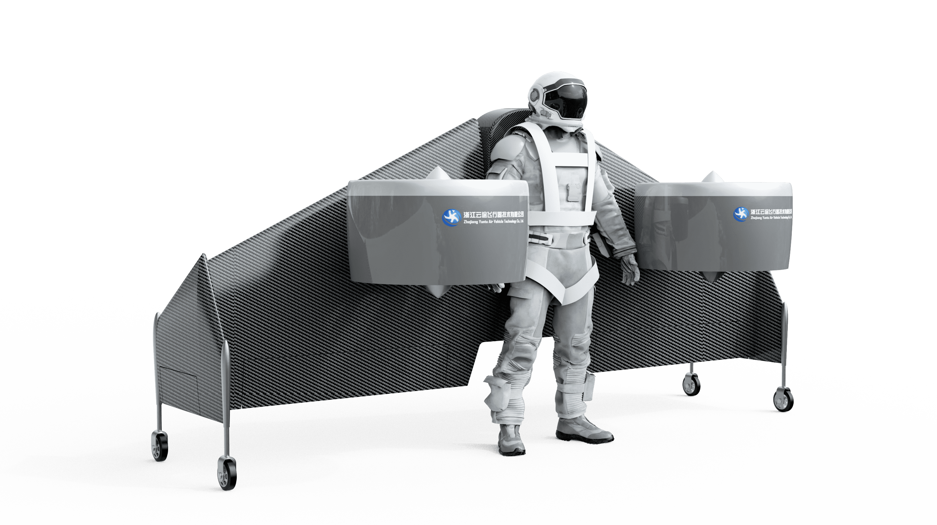
Compound Wing Lift-and-Cruise Architecture
Dedicated vertical lift thrusters are integrated flush within wing bays or wing-tip pods, while high-efficiency rear pusher ducted fans provide continuous forward propulsion without rotor-induced vibration.
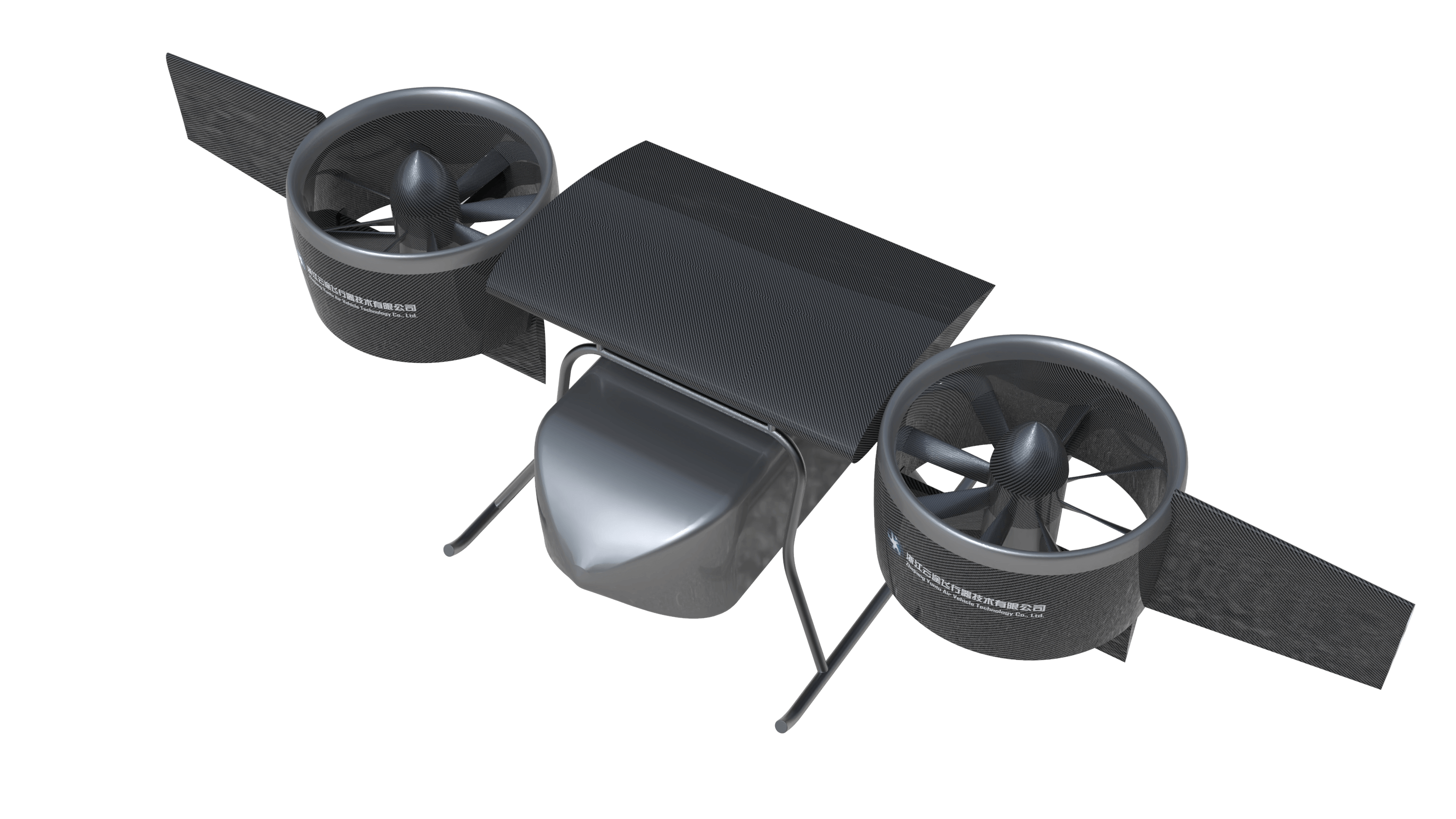
Distributed Electric Propulsion (DEP) Multirotor
A distributed network of 8 to 16 compact ducted units arranged along the perimeter of the fuselage. Micro-clearance containment guarantees full passenger cabin safety even during close-formation operation.
Optimizing Lift-to-Drag & Power Consumption Across Flight Profiles
Traditional open propellers force an engineering compromise between hover disk loading and forward cruise drag. Yuntu ducted units exploit aerodynamic diffusion to excel across every phase.
Vertical Liftoff & Hover (T/W = 1.3 ~ 1.45)
Duct lip suction generates 25%–35% of total hover lift, reducing motor shaft torque requirements and saving up to 18% battery energy during climb-out.
Transition & Airspeed Acceleration (0 – 120 km/h)
Smooth contoured lip geometry maintains attached boundary layers even under high cross-angles of attack, eliminating the buffeting characteristic of open tilt-rotors.
High-Speed Aerodynamic Cruise (180 – 300 km/h)
The low cross-sectional nacelle area produces significantly lower profile drag than large-diameter idling or windmilling open rotors, preserving battery range.
800V DC High-Voltage Bus Architecture & Active Thermal Loop
A continuous megawatt-class powertrain demands extreme efficiency and robust heat dissipation across wide temperature ranges (-40°C to +55°C ambient).
Dual-Channel 800V DC Distributed Bus
Isolated high-voltage DC bus distributing battery energy to nacelle inverters with transient surge suppression and automated pyrotechnic fault isolation.
Silicon Carbide (SiC) Inverter Units
High-frequency SiC power modules integrated directly into the motor aft frame. Reduces thermal footprint while achieving 99.2% switching conversion efficiency.
Pumped Closed-Loop Glycol Cooling
Direct micro-channel cooling jackets surrounding the stator and power electronics. Guarantees zero thermal throttling during sustained maximum-power hover climb.
53 dB(A) Acoustic Signature: The Key to Commercial Vertiport Approval
The primary obstacle facing commercial eVTOL routes in metropolitan business districts and residential areas is community noise rejection. Open rotors emitting piercing 75–85 dB blade passage frequencies risk regulatory curfews. Yuntu ducted fans blend seamlessly into ambient urban soundscapes.
| Observer / Measurement Point | Open Rotor System | Yuntu Ducted System | Vertiport Standard |
|---|---|---|---|
| Vertiport Apron Sideline (30m) | 88 – 94 dB(A) (Harsh BPF screams) | 64 dB(A) (Soft broadband tone) | FAA / EASA Heliport Target: <75 dB(A) |
| Ground Sideline Observer (100m) | 76 – 85 dB(A) (Disruptive low frequencies) | 53 dB(A) (Equal to quiet suburban office) | Urban Vertiport Night Limit: <55 dB(A) |
| Flyover Overhead Altitude (300m) | 68 – 74 dB(A) (Distinct acoustic spike) | 42 dB(A) (Masked by background traffic) | Urban Day Commuter Standard: <50 dB(A) |
* Yuntu ducted propulsors attenuate noise through three complementary layers: acoustic cowl physical shielding, internal micro-perforated Helmholtz liners, and aperiodic rotor blade circumferential spacing.
No Single Point of Failure: 400V–800V DC Distributed Redundancy
Engineered to meet FAA 14 CFR § 21.17(b) Special Class and EASA SC-VTOL Cat. Enhanced requirements (10⁻⁹ catastrophic failure rate for transport category operations).
One-Engine-Inoperative (OEI) Dynamic Restructuring
When any single propulsion branch experiences electrical disconnect, adjacent ducted units ramp phase currents in <80 milliseconds to maintain vehicle hover attitude equilibrium without loss of control.
Dual-Winding High-Voltage PMSM Motors
Electrically isolated dual-redundant stator winding sets driven by dual independent inverters. An internal electrical fault on channel A permits continued 50% power output on channel B.
Ballistic Blade Containment Protection
High-modulus carbon-aramid cowl ring certified to absorb full rotor blade separation energy at 120% redline overspeed, protecting passengers and high-voltage harnesses from uncontained fragments.
High-Noise-Immunity Real-Time Digital Bus
Optically isolated CAN Aerospace and deterministic Ethernet telemetry buses deliver 1,000 Hz real-time closed-loop monitoring of coil temperatures, vibration harmonics, and phase currents.
Four-Phase Propulsion Integration & Airworthiness Roadmap
From initial aircraft aerodynamics down to FAA/EASA TC compliance, our propulsion systems engineering team partners with eVTOL OEMs at every milestone.
Aero Coupling & ICD Freezing
Joint simulation of wing-nacelle aerodynamic interference and structural mount load limits. Freezing mechanical, electrical, and cooling interfaces.
Avionics HIL Closed-Loop Verification
Integrating the propulsion control unit (PCU) with the flight control computer (FCC). Calibrating 20ms dynamic step response and OEI emergency thrust logic.
Transition Wind Tunnel & DO-160G Screening
Full-scale wind tunnel calibration validating cross-wind stability, acoustic damping, and sandstorm / high-temperature continuous durability.
Airworthiness TC Support & Flight Trials
On-site technical support for ground tie-down runs, first hover liftoff, transition flight tests, and formal airworthiness certification documentation.
Engineering Input Checklist for Sizing an eVTOL Powertrain
Our propulsion integration team utilizes 1D momentum codes and full 3D transient Navier-Stokes CFD simulations to deliver tailored propulsion sizing reports. To begin, provide the following initial boundary conditions:
1. Aircraft MTOW & Target Thrust-to-Weight (T/W)
Maximum Takeoff Weight (kg) and minimum hover thrust margin (recommended 1.30–1.40 for OEI).
2. Target Propulsor Count & Spatial Envelopes
Number of ducted thrusters and maximum outer diameter allowed by airframe CAD envelope.
3. DC Bus Voltage Envelope & Current Sag Limit
Nominal and minimum allowable pack voltage under peak hover discharge.
4. Mission Envelope: Cruise Velocity & Operational Temp
Target forward cruise speed, ceiling altitude, and worst-case ambient temperature.
Explore Specialized Industrial UAV Powertrains
Frequently Asked Questions on eVTOL Ducted Powertrain Integration
01Why choose electric ducted fans over open propellers for a passenger eVTOL?+
02How does Yuntu support OEI (One Engine Inoperative) certification requirements?+
03What DC bus voltages are supported for commercial eVTOL architectures?+
04Does Yuntu support custom airframe mounting interfaces and tailored intake cowl geometries?+
05How does cruise drag compare between ducted fans and open propellers?+
06How do eVTOL aircraft manufacturers evaluate powertrain pricing, sizing, and flight testing lead times?+
Accelerate Your eVTOL Airworthiness & Propulsion定型 Program
Collaborate directly with Yuntu aerospace propulsion engineers to receive comprehensive 1D/3D aerodynamic sizing analyses and bus integration datasheets.