
Industrial & Aviation Electric Ducted Fans
In-house OEM R&D and manufacturing across the 60kgf–1000kgf continuous thrust spectrum. Flight-proven test-bench telemetry available. Engineered with micro-clearance shrouds, 53 dB(A) acoustics, and ballistic composite containment.
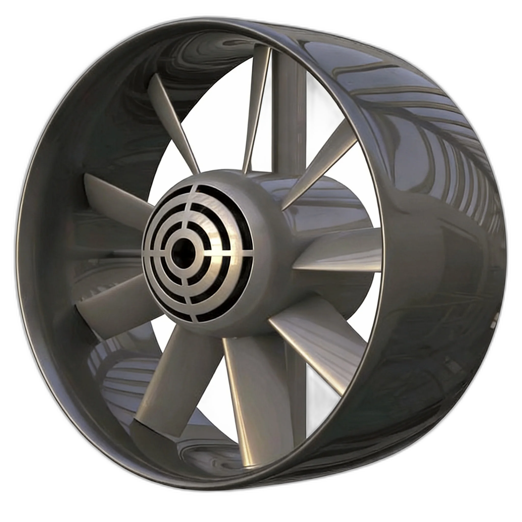
An Electric Ducted Fan (EDF) is an enclosed aeronautical propulsor integrating rotor blades within a cylindrical aerodynamic cowl. By enforcing a 0.8–1.2 mm blade tip clearance, an EDF eliminates 3D tip-vortex induced drag, while its curved intake lip generates forward static pressure suction accounting for 20% to 35% of total hover lift. Yuntu Aircraft manufactures flight-proven propulsion units spanning 60 kgf (588 N) to 1000 kgf (9,800 N) with a 53 dB(A) acoustic signature at 100 meters, compliant with FAA and EASA rotor blade containment standards.
Standard Ducted Propulsion Matrix (60kgf – 1000kgf)
Continuous industrial-grade electric ducted fan units calibrated across ISA sea-level and 45°C high-temperature ambient envelopes. All units are available as integrated propulsors with motor, ESC, and custom nacelle cowls.
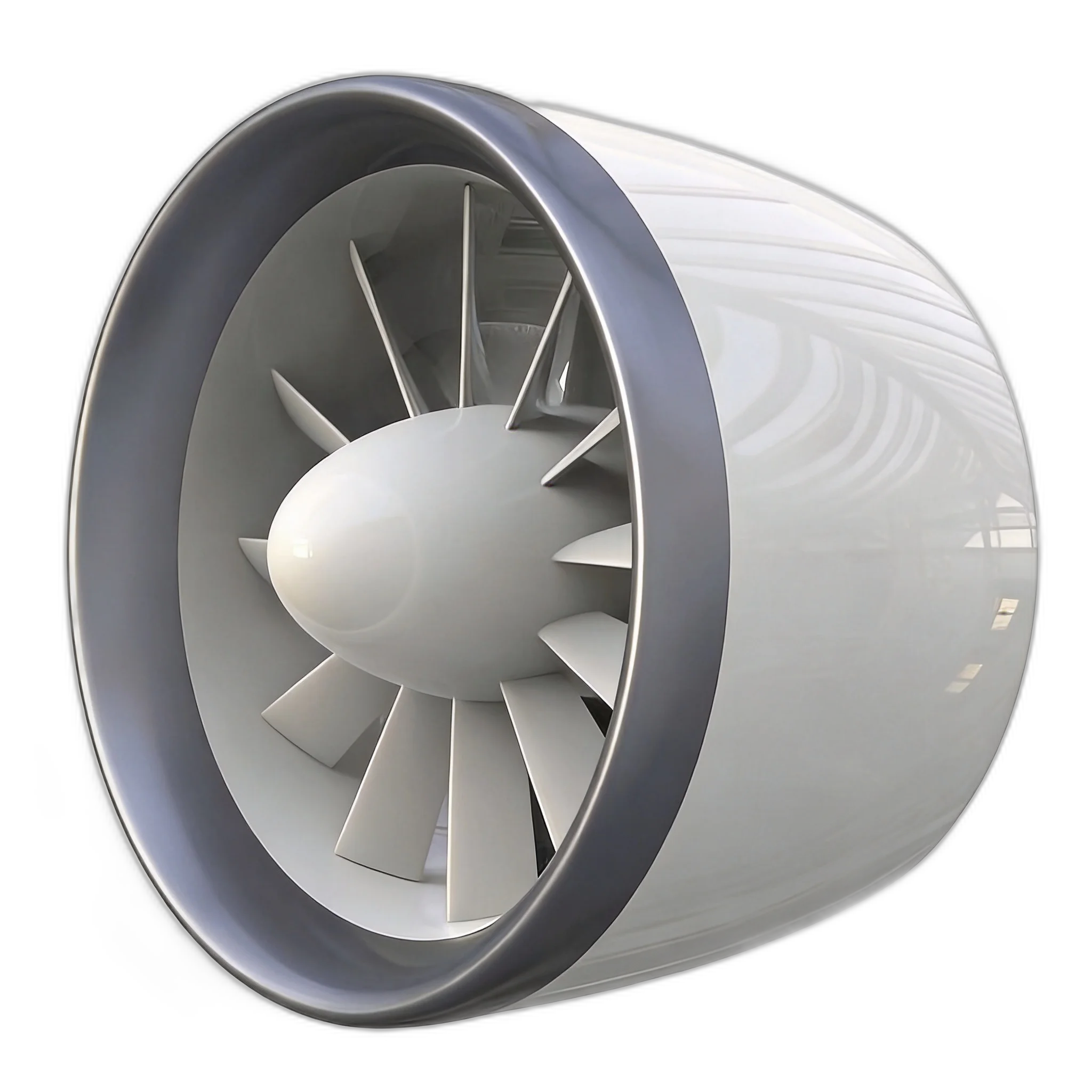
Industrial multirotors, composite wing UAVs, subscale eVTOL demonstrators
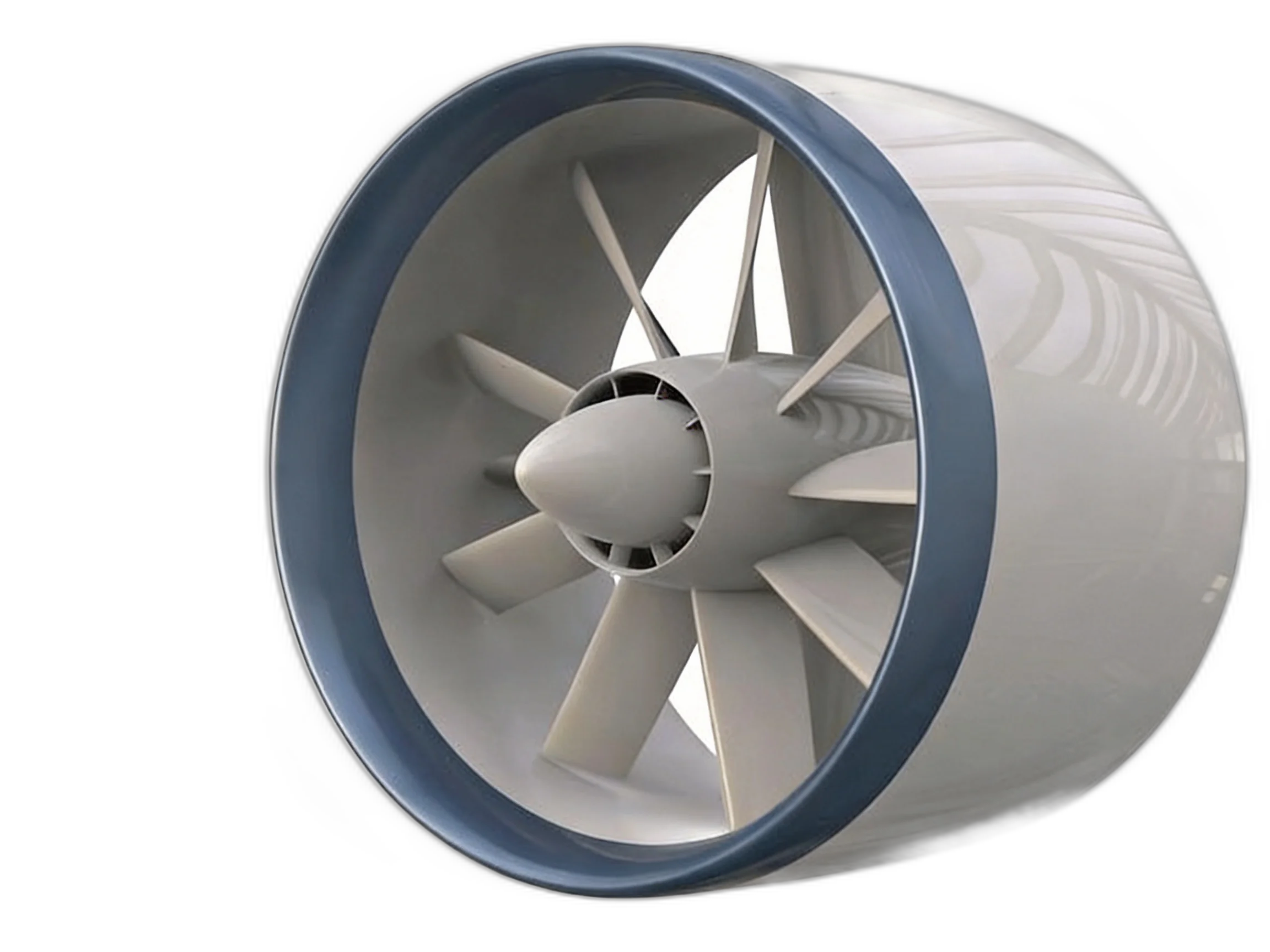
Heavy-lift cargo drones, aerial firefighting, 2-seat light eVTOL platforms
Commercial 4-5 seat passenger eVTOL, regional air mobility, unmanned freight
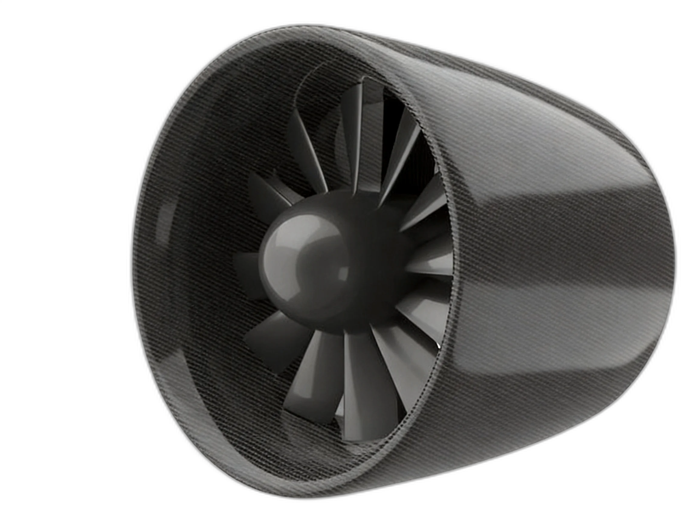
Multi-ton commercial logistics aircraft, distributed regional turboprop replacements
Aviation-Grade Electric Ducted Fan Internal Anatomy
An industrial EDF propulsor is a tightly integrated aerodynamic and electro-mechanical machine. Every millimeter of blade tip gap, every stator curvature, and every composite layer is calibrated for high thrust density and absolute airworthiness.
Aerodynamic Contoured Intake & Nacelle
Engineered with large-radius forward curvature that eliminates flow separation during low-speed high angle-of-attack flight. Forward stagnation pressure suction produces 20% to 35% of total static thrust.
High-Modulus Composite Fan Blade & Rotor Assembly
Aerodynamically twisted wide-chord composite fan blades molded from aerospace-grade T700/T800 carbon fiber prepreg, reinforced with a titanium leading-edge erosion sheath for sand, rain, and debris impact tolerance. Operating at an ultra-tight 0.8–1.2 mm tip clearance, this composite fan blade suppresses 3D tip-vortex dissipation, boosting static ducted propeller thrust by 20% to 35% compared to open propellers of equivalent diameter.
Deswirling OGV Stator Struts
Stationary outlet guide vanes convert rotor swirling rotational momentum back into axial static thrust (recovering 8%–12% kinetic energy) while serving as high-rigidity motor mount struts.
Direct-Drive PMSM Aero Motor
Custom permanent magnet synchronous motor with Halbach magnetic array and direct stator jacket liquid cooling. Eliminates gearbox failure points and electromagnetic interference.
Ballistic Rotor Containment Ring
Multi-layer high-tensile aramid weave integrated into the duct barrel. Validated to absorb 100% kinetic energy of a severed blade at 120% rotor overspeed without outward debris projection.
Helmholtz Micro-Perforated Liner
Acoustic micro-perforated sub-layer tuned to target rotor blade pass frequencies (BPF). Destructive phase cancellation suppresses tonal scream, achieving 53 dB(A) at 100m.
Industry Propulsion Benchmark: Yuntu vs Competitors & Open Rotors
Objective technical comparison across thrust capacity, acoustic footprint, disk loading, aerodynamic safety, and airworthiness containment.
| Evaluation Parameter | Yuntu Electric Ducted Fan | Schübeler eP05-21 Series (DE) | Whisper Aero eQ250 (US) | Equivalent Open Propeller |
|---|---|---|---|---|
| Thrust Coverage Spectrum | 60 kgf to 1000 kgf continuous | 15 kgf to 60 kgf (light industrial) | ~250 lbf (~113 kgf single prototype) | 10 kgf to 800 kgf (requires huge diameter) |
| Installed Diameter Footprint | 520 mm – 1,650 mm (Compact) | 210 mm – 520 mm (Subscale) | ~600 mm (Medium) | 1,800 mm – 3,200 mm (Huge wingspan penalty) |
| 100m Acoustic Footprint | 53 dB(A) (Acoustic liner + low-speed rotor) | 68 – 74 dB(A) (High RPM, unlined duct) | <55 dB(A) (Ultra-high blade count ultrasonic) | 78 – 86 dB(A) (Tip shockwave & blade slap) |
| Static Hover Thrust Gain | +20% ~ +35% (Inlet lip suction integration) | +15% ~ +22% (Moderate lip gain) | +18% ~ +25% (Integrated cowl suction) | 0% Baseline (Severe 3D tip-vortex loss) |
| Rotor Blade Containment | Integrated 120% ballistic Kevlar armor | Lightweight carbon shell (OEM adds ring) | Integrated rim shroud | None (Blade thrown into cabin/fuselage) |
| Ground Personnel Safety | Zero blade exposure, safe for vertiport crew | Enclosed duct (high safety) | Enclosed duct (high safety) | Severe lethal risk from exposed spinning blades |
Eliminating Tip Vortex Induced Losses & Lip Suction Gain
Open propellers suffer from unavoidable high-pressure flow leakage from blade pressure sides to suction sides, wasting 15%–25% of shaft power into turbulent tip vortices. Yuntu ducted fans rewrite fluid boundaries with micro-clearance tolerances and contoured suction lips.
0.8mm – 1.2mm Micro Tip-Clearance Barrier
A high-stiffness structural carbon casing confines rotor blade tips, physically suppressing spanwise cross-flow. The effective aerodynamic aspect ratio increases by 30%, yielding uniform lift distribution across span.
Intake Lip Suction Integral (∮ P·dA)
As air accelerates through the high-curvature contraction shroud, localized static pressure plunges over the lip curve. Surface pressure integration yields a net positive axial forward force contributing 20% to 35% of total static hover thrust.
Integral Stator Deswirl Recovery
Aero-designed structural stator vanes located 1.5 rotor chord lengths downstream deswirl high-speed rotational flow, converting angular momentum into usable axial thrust while dampening motor thermal load.
Propulsion Matching: Real-World Sizing & Numerical Cases
Engineering derivations illustrating how Yuntu ducted fans scale across composite wing UAVs, heavy-payload cargo platforms, and commercial passenger eVTOLs.
Long-Endurance Surveillance / Pipeline Patrol
During vertical takeoff, the 4 lift units operate at 50% throttle (7.2 kW each), providing 120 kgf steady hover plus 120 kgf gust control margin. In forward flight, lift fans are blanked off while the single tail pusher requires only 18 kgf (2.8 kW) to sustain 130 km/h cruise speed.
Middle-Mile Cargo / Aerial Firefighting
4 × 200kgf units deliver 800kgf total thrust at 350V DC bus. If One Engine Inoperative (OEI) occurs, the remaining 3 units automatically boost to 120% emergency rating (240kgf each, totaling 720kgf), ensuring safe hover landing without losing vehicle attitude control.
Urban Air Mobility (UAM) Air Taxi
Distributing 4,000kgf installed thrust across 8 units allows low disk-loading operation at hover, keeping noise below 53 dB(A) at 100m for downtown vertiport landing. In transition, tilting nacelles provide high dynamic pressure, accelerating the aircraft to 260 km/h fast cruise.
Slashing Discrete Harmonics Down to 53 dB(A) at 100m
Urban Air Mobility (UAM) vertiport certification hinges upon neighborhood acoustic acceptance. While open rotors generate piercing blade passage frequencies (BPF), Yuntu ducted propulsors combine nacelle shielding with tuned micro-perforated liners.
Micro-Perforated Helmholtz Resonator Liners
Internal cowl walls incorporate micro-perforated damping layers targeting the 1,000 Hz – 4,000 Hz human-sensitive auditory spectrum, attenuating discrete tonal whine by >18 dB.
Aperiodic Rotor Blade Phase Modulation
Rotor blades are arranged using aperiodic circumferential pitch angles, diffusing acoustic harmonic summation into soft, wideband pink/white background noise.
Acoustic Directional Shielding
The cylindrical cowl acts as a barrier, preventing radial dipole noise radiation from projecting downward toward ground communities.
Ballistic Rotor Blade Containment & Structural Redundancy
Compliant with CAAC CCAR-23/27, FAA 14 CFR Part 23, and EASA SC-VTOL requirements, Yuntu ducted fans guarantee complete kinetic containment during uncontained blade liberation events.
Ballistic Aramid-Carbon Energy Absorbing Casing
The outer duct shell integrates multi-layer high-modulus aramid (Kevlar) fibers co-cured with aerospace-grade carbon prepreg under high-temperature autoclave processes. In bench tests simulating full blade release at 120% redline overspeed, the containment ring absorbs 100% of kinetic energy without shell perforation.
- ▹FAA Part 23 / 21.17(b) Special Class Criteria
- ▹EASA SC-VTOL.2225 & SC E-19 Electric Propulsion Standards
- ▹CAAC CCAR-23 Rotorcraft Airworthiness Regulations
- ▹DO-160G Environmental Conditions for Airborne Equipment
OEM Propulsion System Integration
Developing manned passenger or heavy freight eVTOL aircraft? Explore our dedicated system solutions across tilt-duct, compound wing, and DEP multirotor architectures.
Explore eVTOL Propulsion Solutions →Full-Scale Wind Tunnel & Dynamometer Verification
Anechoic Aerodynamic Wind Tunnel
Continuous flow testing validating cruise drag, dynamic transition angles (0° to 90°), and lip boundary layer stability.
Multi-Axis Multi-Parameter Dynamometer Rig
Precision load cells recording axial thrust, rotor torque, bus voltage sag, and phase current step responses.
High-Temperature & Dust Environmental Chamber
Continuous 100-hour endurance test in 50°C ambient temperatures with 0.5–50μm silica quartz dust injection.
Frequently Asked Technical & Procurement Questions
01What is a ducted propeller, and how does ducted fan vs propeller thrust compare?+
02What is the primary aerodynamic advantage of an electric ducted fan over a propeller?+
03How do Yuntu ducted fans meet urban vertiport noise regulations?+
04Does Yuntu supply standalone components or turnkey integrated propulsion systems?+
05Can the 60kgf–1000kgf units operate in extreme desert conditions?+
06What initial parameters are required from an OEM to size a ducted powertrain?+
07Is an electric ducted fan the same as an "Electric Jet"?+
08Can Yuntu ducted aerodynamic and acoustic technology be adapted for industrial cooling towers or data centers?+
Integrate Certified Ducted Propulsion into Your Flight Platform
Connect directly with Yuntu powertrain architects to evaluate thrust-to-weight margins, bus electrical matching, and CAD integration models.