
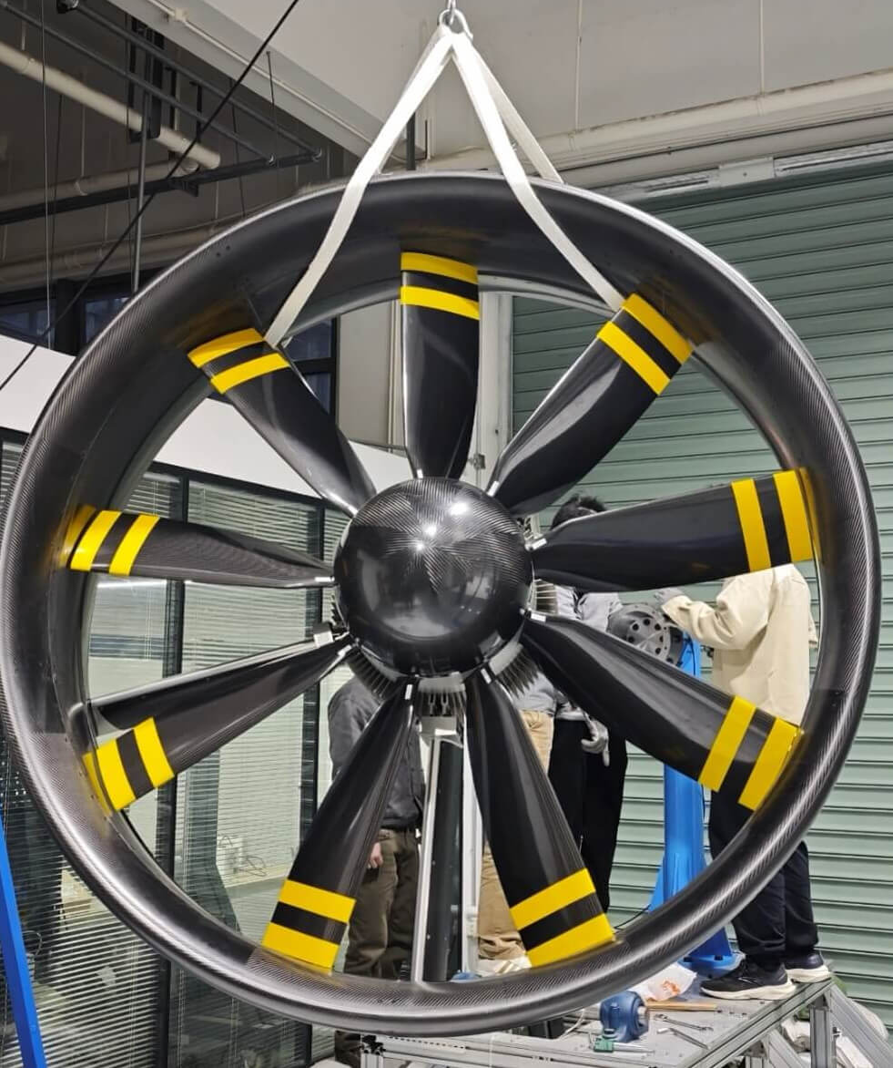
Reference Configuration Specifications
Standard Engineering Envelope & Baseline Performance
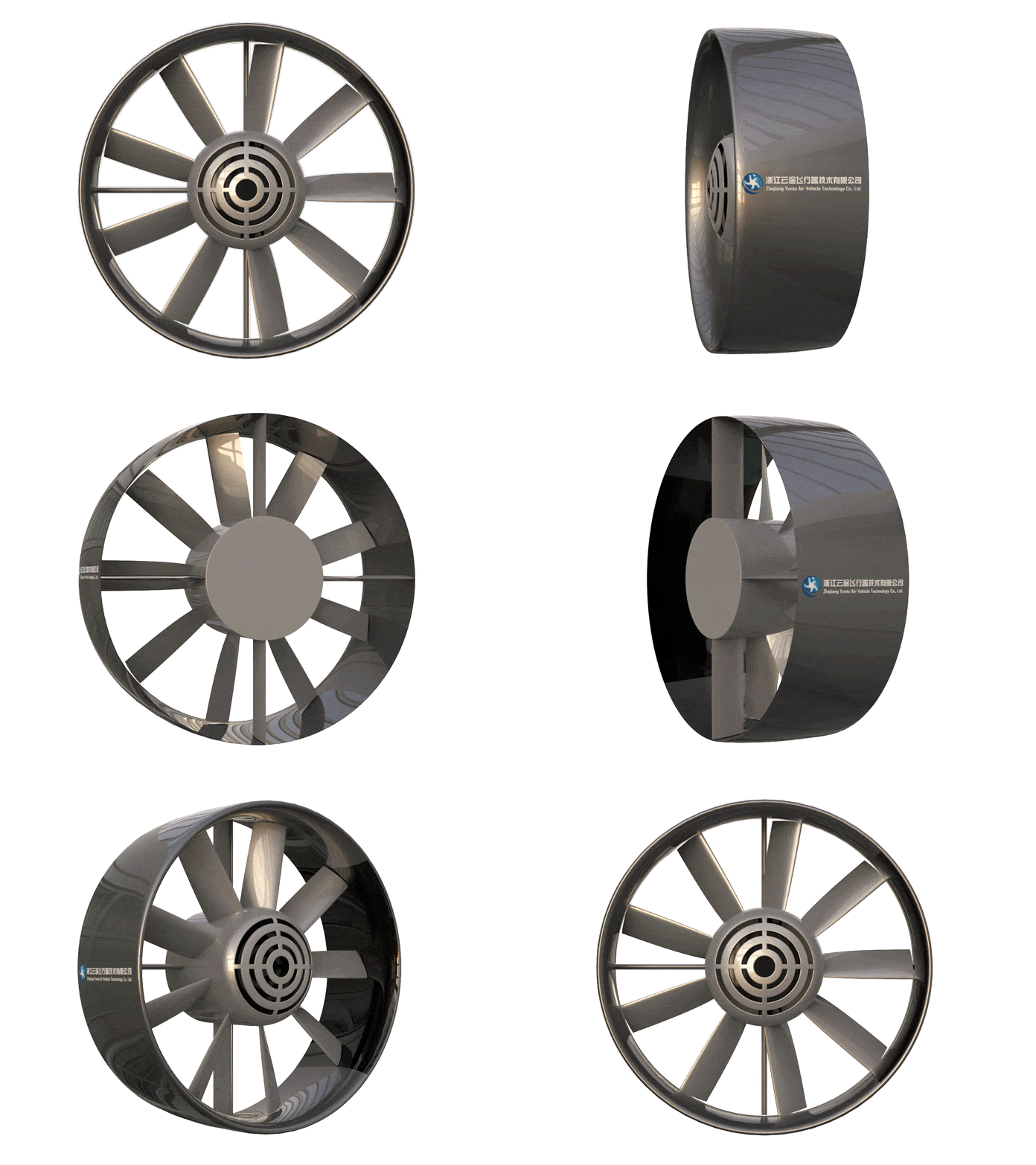 Dynamic 3D Cutaway (9 Blades / 7 Stator Vanes)
Propulsion Engineering Innovations
Combines ultra-high electrical efficiency with fault-tolerant dual-winding safety and severe sandstorm/coastal environment durability.
120 kW Redundant Dual-Winding Motor
Features electrically isolated dual-channel stator windings. In the event of an inverter or phase leg fault, the propulsion unit maintains over 60% rated thrust, ensuring critical climb gradient safety.
Diffusion Duct Aerodynamic Optimization
1.9m wide-aperture composite cowl with boundary layer ingestion (BLI) diffusion geometry. Achieves an 18% reduction in specific energy consumption during forward cruise compared to traditional open rotors.
Inertial Sand-Separation & Hardened Leading Edges
Nickel-cobalt electroplated rotor blade leading edges and integrated labyrinth sand-shedding nacelle contours, rigorously proven in 100-hour desert sandstorm test chambers.
600V–800V Wide-Bandgap Motor Controller
Silicon Carbide (SiC) MOSFET architecture delivering 98.5% peak electrical conversion efficiency with advanced partial-discharge suppression at altitudes up to 5,000m MSL.
Target Aircraft Configurations
Directly validated power distribution models for heavy regional freight drones and 2–4 place utility electric aircraft.
1.5–2.8 Ton Heavy Freight Logistics Aircraft
Quad-thruster or hex-thruster tilt-wing configuration providing 20–30 kN total hover thrust with 500+ kg payload capacity across 350 km logistics corridors.
2–4 Place Electric Personal & Training Aircraft
Fuselage-integrated or wing-pylon mounted twin pusher configuration offering whisper-quiet takeoff profiles and reduced runway climb distances.
High-Speed Hydrofoil & Amphibious Support Craft
Surface-skimming aeropropulsion avoiding underwater debris damage and cavitation erosion while delivering rapid acceleration up to 55 knots.
Aerospace Engineering Deliverables
Comprehensive digital integration assets provided directly to airframe structural and avionics development teams.
Full-Scale Wind Tunnel 6-DoF Calibration Dataset
High-precision load cell datasets covering airspeeds up to 55 m/s and continuous yaw/pitch deviations, enabling precise flight control simulator modeling.
Parametric 3D CAD & Digital Twin Package
Millimeter-accurate mounting interface coordinates, detailed mass property matrices, and structural finite element models (Nastran/Ansys).
Flight-Control Avionics Interface (ICD)
Complete bus communications manual supporting CAN Aerospace, ARINC 429, and PWM fallback lines with hardware watchdog monitoring.
Multi-Altitude Propulsion Performance Map
Comprehensive thrust, torque, RPM, and cooling fluid temperature charts mapped across 0 to 5000m ISA density altitudes.
Need Full 3D CAD/STEP Models & Avionics Protocols?
Yuntu provides OEM aircraft design teams with mounting flange CAD, mass moment matrices, and CAN/ARINC ICDs.
Frequently Asked Questions
Related Engineering Deep-Dives
 Environmental Test Report
Extreme Environment Qualification: 52°C Heat & Heavy Sandstorm Environmental Chamber Test Report
Official 150-hour qualification test logs in 52°C ambient heat and continuous silica sandstorms. Verified PMSM stator thermal balance and IP67 labyrinth seals.
 Architecture & Strategy
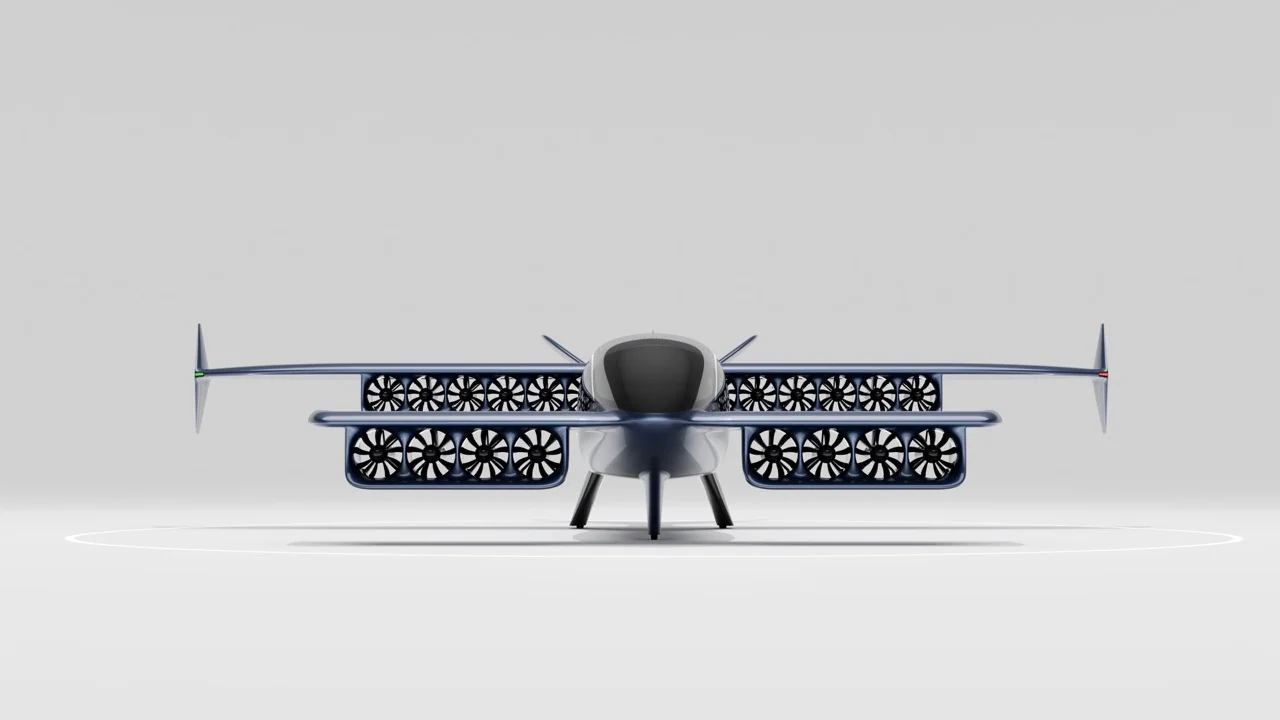
Distributed Electric Propulsion (DEP) Architecture: Tandem-Wing Aerodynamics & Civil Aviation 10⁻⁹ Safety
Why distributed electric propulsion combined with tandem wings replaces complex tilt-rotor mechanisms and unlocks civil aviation 10⁻⁹ airworthiness safety.
Compatible Airframe Solutions for 500kgf System
Regional & Passenger Aviation Powertrains
High-thrust electric ducted fan powertrains with 600V–1000V high-voltage bus and full rotor containment safety.
Heavy Lift & Industrial Logistics
Overcoming the open-propeller scaling trap with 20-35% lip suction thrust gain and hot-turnaround cargo safety.
Distributed Multi-Thruster Powertrain
Compact multi-thruster distributed powertrain arrays with 53dB acoustic stealth and OEI safety margins.
Partners