
Custom Electric Ducted Fan Propulsion Systems
Bespoke aerodynamic nacelles, custom high-voltage motor windings, and turnkey distributed powertrain integration for mission-critical aircraft.
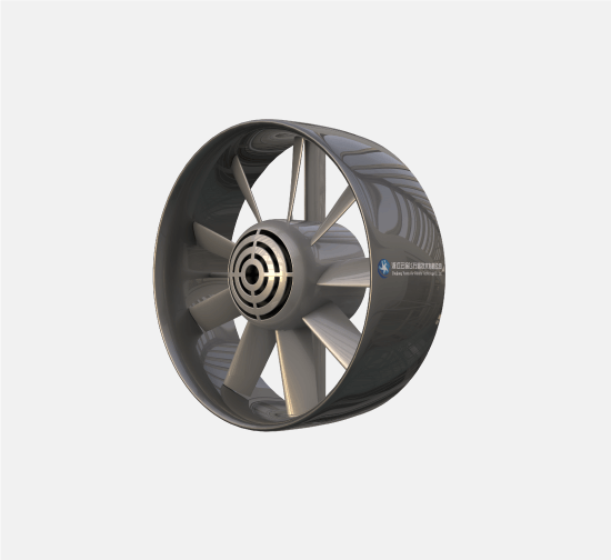
Yuntu provides full-lifecycle custom electric ducted fan (EDF) propulsion development across 5kgf to 1000kgf+ thrust classes. Our engineering covers non-standard area ratios, aviation carbon composite layups with ballistic Kevlar containment, 400V–800V SiC motor winding optimization, and structural pylon integration. Standard prototype delivery is 4 to 6 weeks with comprehensive wind tunnel and dynamometer test certificates.
Aerospace Engineering Customization Across 4 Physical Domains
When off-the-shelf commercial propulsion fails to meet constrained airframe envelopes or high-voltage bus architectures, Yuntu delivers mission-optimized bespoke propulsion engineering.
Nacelle Geometry & Convergence Area Ratio
Full Navier-Stokes computational fluid optimization of inlet lips, diffusion angles, and stator vane swirl recovery tailored to mission transition profiles.
- Inlet lip radius optimization for tilt-wing transition and high-alpha inflow
- Nozzle exit area ratio calibrated to cruise speed (100–280 km/h)
- Ultra-tight 0.8–1.2mm dynamic tip clearance carbon shrouds
Aviation Carbon Layup & Ballistic Containment
Autoclave-cured T700/T800 composite structures with integrated Kevlar containment rings complying with aerospace airworthiness standards.
- Multi-axial carbon fiber plies optimized for gyroscopic bending loads
- Full blade containment certified up to 120% nominal overspeed
- Structural stator struts transferring up to 1000kgf thrust load into the airframe
Custom Motor Windings & SiC Inverter Tuning
Dedicated stator lamination geometries and bespoke Kv windings matched to 400V–800V Silicon Carbide aviation battery architectures.
- Target Kv calibration for peak torque at specific cruise RPM sweet spot
- High-voltage corona-resistant insulation (Class H, 180°C thermal endurance)
- Silicon Carbide (SiC) inverters with field-oriented vector control (FOC)
Structural Pylon Mounts & Avionics Telemetry
Titanium load-bearing interfaces and redundant telemetry protocols engineered directly into the nacelle structure for turnkey integration.
- Bespoke titanium/aluminum pylon bracket interfaces matching aircraft spar hardpoints
- Dual-redundant CAN-FD, RS-422, and PWM bus control interfaces
- Integrated temperature, vibration, and stator strain gauge telemetry channels
Platform Baseline Derivative Families (60kgf to 1000kgf+)
To minimize program development lead times, custom engineering programs can be derived directly from Yuntu mature baseline propulsion units.
YTN-60 Derivative (Industrial Compact)
Slimline nacelle, low acoustic signature, IP67 weatherproofing
YTN-200 Derivative (Aviation Mid-Thrust)
High-voltage winding, 400V/800V SiC matching, tilt-mount pylon
YTN-500 Derivative (Heavy Logistics)
Kevlar ballistic containment, high-torque winding, dual-bus redundancy
YTN-1000 Derivative (Aviation Flagship)
DEP array clustering, 800V+ SiC inverter integration, CCAR/FAA compliance
Aircraft Architecture Integration Paradigms
Engineered custom solutions developed for specific flight dynamics and airframe configurations.
eVTOL Tilt-Wing / Tilt-Rotor Pods
Vertical hover transitioning to 220 km/h forward flightHeavy-Lift Multirotor Compact Array
High-precision hover in gusty conditions (Beaufort 6)Fixed-Wing Fuselage Tail-Pusher
160–260 km/h sustained economic transitDistributed Electric Propulsion (DEP) Wing
Continuous high-lift blown-wing operationsAirworthiness Engineering Documentation Package
Every custom propulsion program delivers production-ready aerospace engineering documentation for aircraft certification.
1D Momentum & 3D CFD Aerodynamic Polar Package
Calibrated thrust vs. power, mass flow, pressure distribution, and exit velocity maps across 0–300 km/h.
Native 3D STEP Envelope & Pylon Load Interface Definition
Exact mechanical envelope, mounting fastener specs, center-of-gravity (CG), and moments of inertia (MOI).
Aero-Structural FEA & Modal Resonance Analysis Report
Stress distribution under 6G maneuver loads, gyroscopic precession fatigue, and modal resonance margin.
Blade-Out Containment Certification Dossier
Numerical simulation and physical spin-rig evidence demonstrating zero-casing penetration at 120% redline RPM.
Official Dynamometer Bench Test Certificate
Factory-calibrated voltage, current, RPM, static thrust, torque, acoustic footprint, and thermal equilibrium curves.
Interface Control Document (ICD) & CAN-FD DBC Package
Complete register map, telemetry diagnostics definitions, and fail-safe throttle governance protocols.
Propulsion R&D & Test Infrastructure
Our state-of-the-art laboratory facilities ensure all performance metrics are physically measured and empirically validated.
Inlet lip flow separation, dynamic crosswind response, acoustic array noise mapping.
Step-response torque calibration, continuous endurance hovers, motor thermal saturation curves.
Aviation-grade T700/T800 prepreg carbon fiber consolidation with void fraction <0.5%.
Bearing seal integrity, blade leading-edge abrasion resistance, thermal equilibrium in extreme climates.
Interactive Propulsion Specification Builder
Input your airframe design parameters to calculate preliminary thrust margins and generate customized powertrain recommendations.
5-Stage Closed-Loop Aerospace Delivery Lifecycle
A formal systems engineering development process ensuring zero aerodynamic guesswork and absolute compliance with aircraft specifications.
Mission Profiling & Envelope Sizing
Aircraft MTOW, hover/transit thrust margins, voltage limits, geometric envelope
3D CFD & Aero-Structural FEA
Compressible Navier-Stokes blade optimization, modal vibration, thermal equilibrium
Tooling Fabrication & Winding
Precision CNC negative molds, carbon autoclave curing, custom stator coil winding
Full-Power Rig Calibration
High-voltage dynamometer endurance, acoustic microphone array, sealing verification
Flight Integration & Serial Supply
Airframe flight trial telemetry tuning, production tooling lock, series manufacturing
Catalog Propulsion Units vs. Yuntu Custom Engineering
Direct quantitative comparison between standard commercial units and bespoke mission-engineered propulsion systems.
| Engineering Dimension | Catalog Commercial Units | Yuntu Custom Engineered System | Mission Performance Advantage |
|---|---|---|---|
| Inlet Lip & Nacelle Aerodynamics | Fixed circular cylindrical lip | Asymmetric cambered lip tailored to forward cruise / tilt angles | +15% to +25% transition thrust reserve without flow detachment |
| Motor Winding & Kv Calibration | Fixed catalog winding (stepped Kv increments) | Precision winding matched to exact bus voltage & cruise RPM | Operates in peak 96%+ efficiency sweet spot under continuous duty |
| Airworthiness Ballistic Containment | Unshielded or heavy aluminum ring | Integrated Kevlar aramid multi-layer ballistic containment liner | FAA Part 23 airworthiness compliance with minimal parasitic weight |
| Airframe Structural Mounting | Generic rear faceplate bolts | Monocoque composite/titanium pylon transferring primary loads | Eliminates redundant brackets, reducing airframe dry mass by 12% |
| Avionics Telemetry & Redundancy | Basic PWM throttle signal | Dual-redundant CAN-FD bus with real-time temperature, vibration & current | Supports predictive health monitoring and sub-millisecond OEI fail-safe recovery |
Frequently Asked Questions on Custom Powertrain Engineering
01What is the standard development lead time for an A-Sample custom EDF prototype?+
02What is the Minimum Order Quantity (MOQ) for custom engineering programs?+
03Can you customize the ducted fan to fit our proprietary airframe nacelle cavity?+
04What bus voltages and power inverter architectures are supported?+
05Do custom units include certified test and airworthiness reports?+
06Can you support Distributed Electric Propulsion (DEP) synchronization?+
07How should an OEM evaluate payload capacity and thrust-to-weight ratio before starting customization?+
08Does Yuntu support custom aeroacoustic design for low-noise industrial cooling and data-center fans?+
Ready to Engineer Your Bespoke Propulsion System?
Submit your airframe boundary conditions to consult directly with Yuntu aerospace propulsion engineers.