
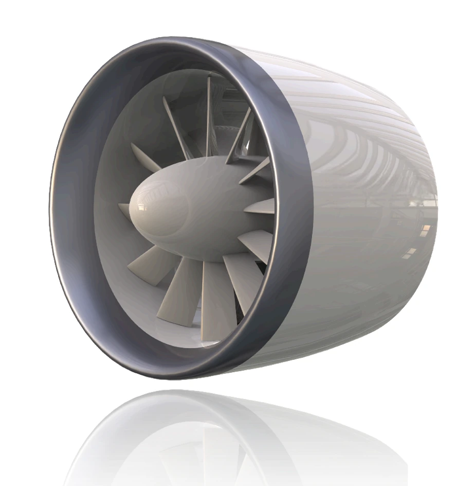
Standard 60 kgf-class electric ducted fan (EDF) platform baseline configuration with 9-blade rotor, aerodynamic spinner cone, and low-drag nacelle.
Reference Configuration Specifications
Standard Engineering Envelope & Baseline Performance
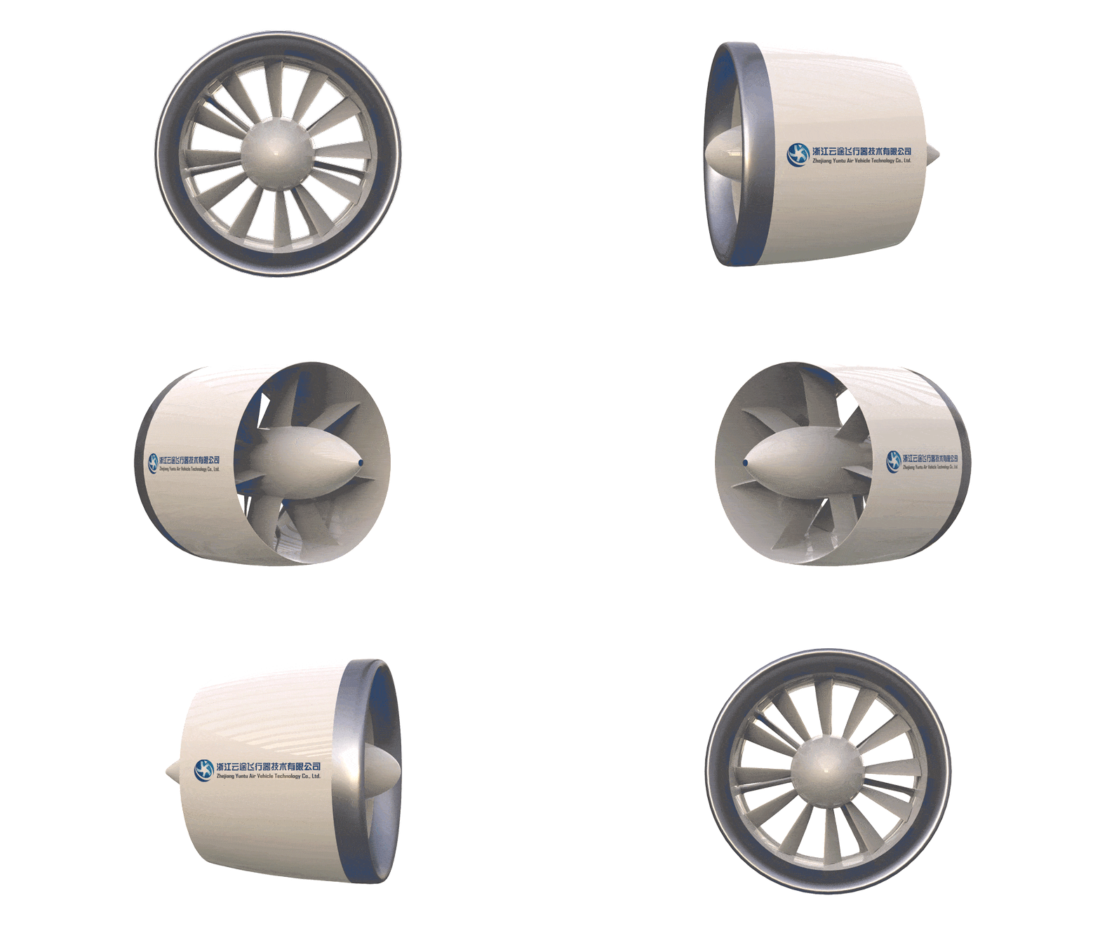 Dynamic 3D Cutaway (9 Blades / 7 Stator Vanes)
Customization Capabilities
Unlike a fixed catalogue product, the YUNTU 60 kgf-class EDF platform can be tailored across 6 key engineering dimensions:
Target Static & Cruise Thrust
Thrust ratings and RPM curves calibrated for specific takeoff rotation, climb transition, and high-efficiency cruise profiles.
Duct Diameter & Installation Envelope
Outer shroud contours, lip radius, and mounting brackets adapted for wing-submerged, flush-bay, or pylon configurations.
Voltage Platform & Power Architecture
Configurable for 100V to 400V+ DC buses, high-discharge battery packs, fuel cells, or hybrid range extenders.
Motor & ESC Selection
Custom stator windings, magnetic Halbach arrays, and high-frequency SiC/GaN aviation ESCs tuned to mission duty cycles.
Cooling Conditions & Airflow Environment
Passive nacelle bypass cooling or active liquid cooling cold plates evaluated per airframe climb and cruise thermal profiles.
Control Interface & Flight Control Integration
Redundant PWM, DShot, CAN Aerospace, and RS-485 interfaces with low-latency telemetry for integrated flight control computers.
Preliminary Performance Curve
The chart displays the preliminary RPM–thrust–power relationship of one tested motor/ESC configuration of the YUNTU 60 kgf-class EDF platform. Provided for initial technical evaluation.
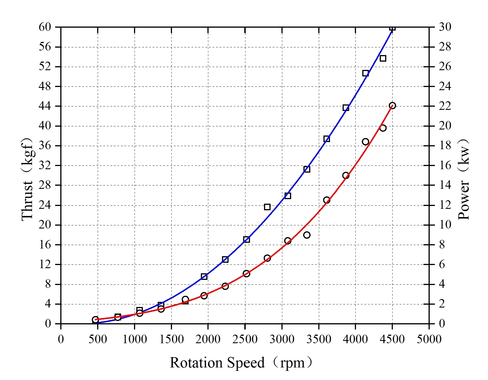
Select an RPM to view approximate thrust and power read from the supplied curve, not raw test data. The power definition depends on the test setup:
Engineering Note:Rated takeoff operating speed for vertical takeoff and maximum acceleration.
EDF testing and validation
Rigorous ground test bench verification logging multi-axis thrust, torque, input power, and motor thermal telemetry under calibrated dynamometer testing.
 Testing & ValidationView Full Image
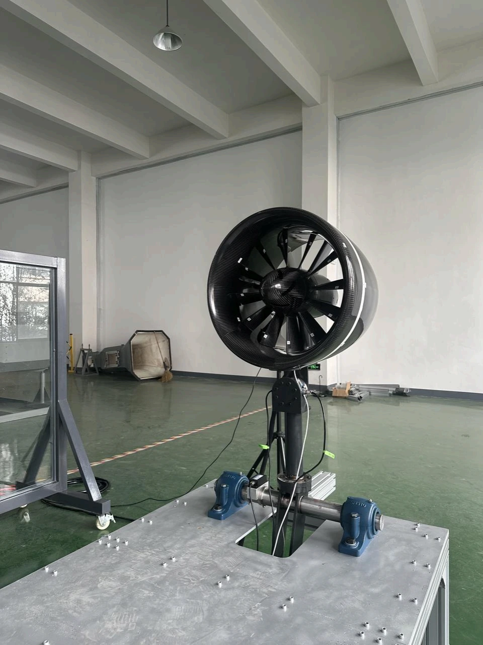
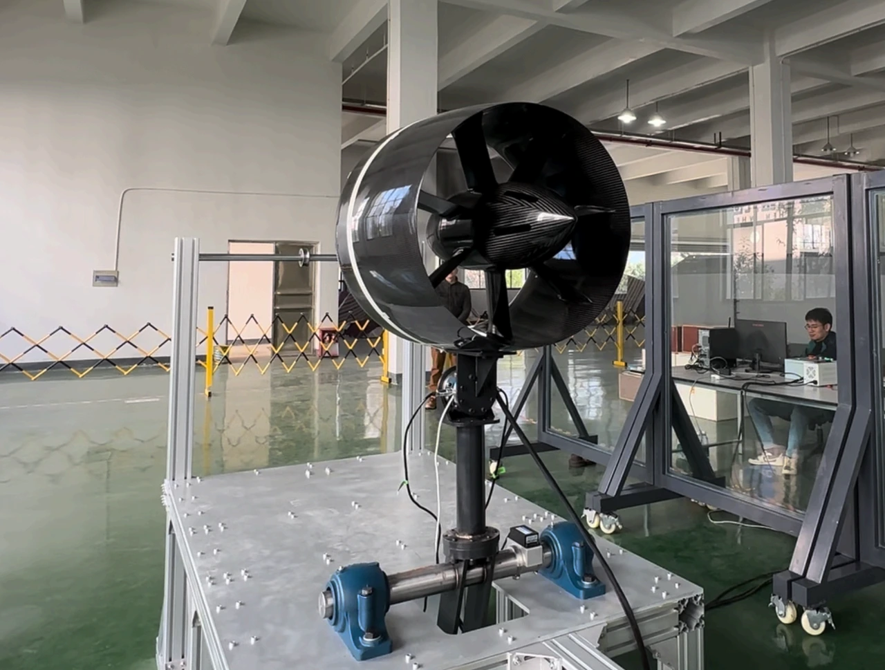
EDF testing and validation (Dynamometer Rig & Thrust Sensors)
Mounted onto the heavy industrial dynamometer test bench with high-accuracy load sensors and shaft encoders, logging continuous 0–5,000 RPM step-loading telemetry.
 Testing & ValidationView Full Image
EDF testing and validation (Engineering Control & Telemetry Station)
Exhaust outlet showing stator guide vanes and aerodynamic tailcone, alongside the engineering telemetry station monitoring real-time voltage, current, and thermal profiles.
Book 60kgf Technical Datasheet & Test Report
Direct consultation with Yuntu engineering team for 0~5,000 RPM telemetry datasets and integration guidance.
Key Engineering Advantages
Engineered for maximum propulsive efficiency, multi-thruster distributed airframes, and full-spectrum aircraft integration support.
Configurable Thrust Class
Tailored static and cruise thrust ratings matching airframe flight envelopes, delivering up to 60 kgf maximum class thrust based on aircraft-level specifications.
Integrated Duct, Fan, Motor & ESC Solution
A turnkey, fully integrated propulsion unit uniting aerodynamic duct, 9-blade carbon rotor, high-RPM electric motor, and matched aviation motor controller.
Distributed Multi-Thruster Readiness
Compact 0.60 m fan diameter and streamlined 0.72 m outlet geometry engineered for wing-embedded distributed electric propulsion and blown-lift architectures.
Proprietary Aerodynamic Optimization
In-house developed 9-blade rotor and 7-vane stator configuration eliminating transonic tip loss and delivering exceptional thrust-to-power efficiency.
Fast Algorithmic Customization
Parametric propulsion design algorithms and mature software tools enabling fast engineering turnarounds for custom duct envelopes and voltage buses.
Aircraft-Level Propulsion Integration
Direct engineering partnership covering inlet/outlet flowfield integration, nacelle embedding, cooling environment analysis, and avionics ICD matching.
Aircraft–Propulsion Integration Guide
EDF performance is strongly influenced by aircraft-level integration. YUNTU provides multi-disciplinary engineering partnership from airframe concept to flight trials.
Inlet & Outlet Airflow Optimization
Inlet lip radius, duct diffuser expansion ratio, and boundary layer ingestion (BLI) must be matched to airframe angle of attack and forward airspeed to eliminate separation.
Installation Envelope & Airframe Embedding
Optimized for wing-submerged, flush-bay, or podded pylon mountings. High-modulus carbon composite shroud provides 360-degree blade containment and structural rigidity.
Thermal Management & Cooling Environment
Motor and ESC thermal management must be validated against hot-day climb profiles (ISA +30°C) via dedicated airflow channels or liquid heat exchanger jackets.
Bus Voltage & Flight Control Coupling
Sub-5ms telemetry latency over CAN Aerospace bus ensures synchronized RPM response across multi-thruster arrays for precise attitude stabilization.
 Enlarge
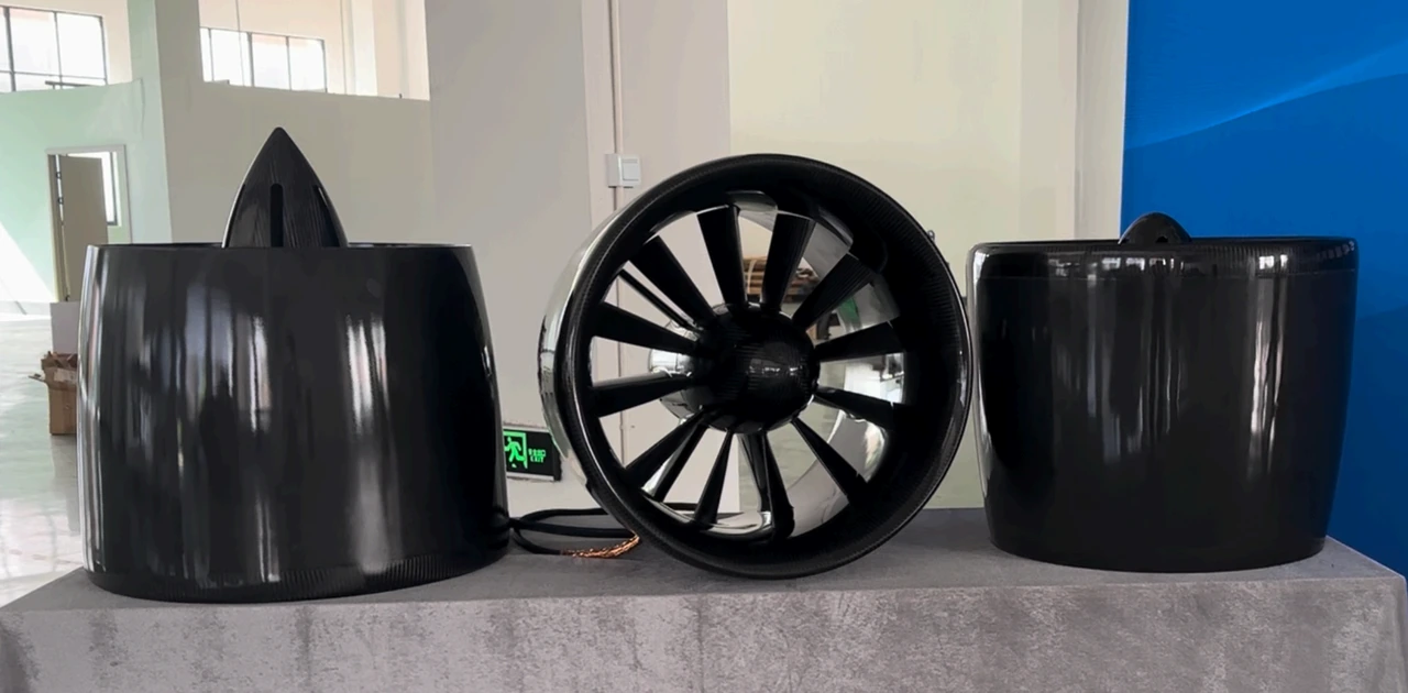
Customized EDF configuration based on customer requirements
Three-piece modular carbon composite architecture (nacelle cowling, integrated core thruster, and aerodynamic casing) engineered for wing-embedded, podded, and turbojet-to-electric conversion airframes.
Turbojet-to-Electric Propulsion Conversion Studies
For turbojet-to-EDF conversion projects, YUNTU recommends jointly defining the propulsion configuration together with the overall aircraft architecture, aerodynamic characteristics, power system, thermal management, and flight control logic. Aircraft–propulsion integration is not limited to the engine or propulsor itself; it also involves aerodynamic, structural, electrical, control, and subsystem interfaces between the propulsion system and the airframe.
Typical Aircraft Applications
Engineered for advanced airframes requiring high static thrust, enclosed rotor safety, and clean electric propulsion integration.
VTOL Fixed-Wing & Hybrid-Lift UAVs
Dual or quad ducted thrusters providing vertical takeoff and clean transition into forward cruise. Operating at 2,500 rpm cruise speed maximizes aerodynamic efficiency and corridor range.
Industrial Heavy-Lift Cargo UAVs
Distributed multi-rotor cargo platforms where ducted shrouds provide personnel safety during cargo ground handling, eliminate blade tip collisions, and offer 20%+ lip suction thrust gains.
DEP Blown-Wing & Multi-Thruster Airframes
Multi-thruster wing-embedded arrays utilizing boundary layer ingestion (BLI) to re-energize wing wake, increase lift coefficient, and reduce takeoff/landing stall speeds.
Turbojet Replacement & Conversion Projects
Direct electric conversion for experimental and light UAV airframes previously powered by micro-turbojet engines, offering low thermal signature, low acoustic signature, and reduced operating cost.
Aerospace Engineering Data Package
Comprehensive documentation and digital twin data provided to airframe design and certification teams.
Calibrated Static & Dynamic Thrust Matrix
High-precision test bench data covering 10% to 100% throttle steps, RPM, voltage, current, input power, and dynamic forward airspeed response.
High-Fidelity 3D STEP & Mounting Interface
Parametric STEP/IGES model detailing mounting flange bolt patterns, center of gravity (CG), mass moments of inertia, and finite element boundaries.
Avionics Bus Protocol (PWM / CAN / ARINC)
Complete software and electrical ICD covering CAN Aerospace telemetry, heartbeat monitoring, thermal watchdog, and closed-loop speed control.
Continuous Full-Duty Endurance Test Report
Rigorous endurance trial logs documenting bearing temperature stability, vibration spectral acceleration, and stator winding thermal rise.
Need Full 3D CAD/STEP Models & Avionics Protocols?
Yuntu provides OEM aircraft design teams with mounting flange CAD, mass moment matrices, and CAN/ARINC ICDs.
Technical Evaluation & Integration FAQ
Related Engineering Deep-Dives
 Technology Deep-Dive
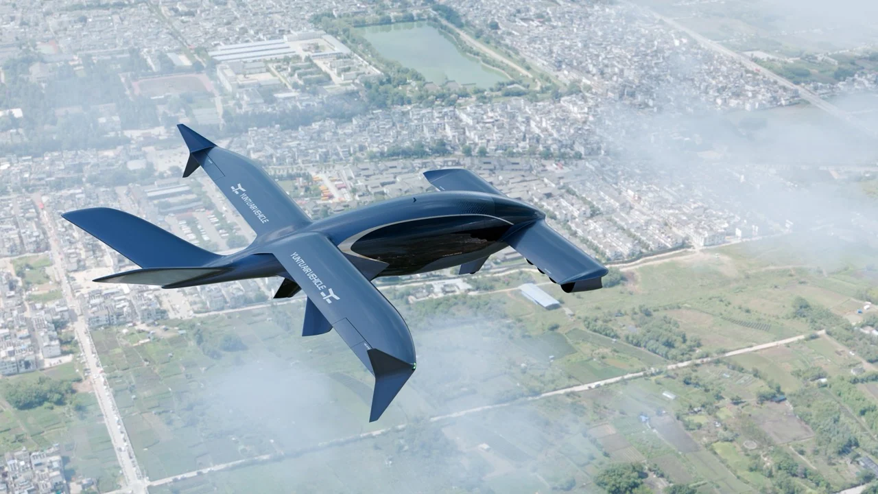
Electric Ducted Fan (EDF) vs Open Propellers: Aerodynamic Efficiency, 53 dB Acoustics & Containment Airworthiness
Explore fluid mechanics of electric ducted fans vs open propellers: tip-vortex loss, lip suction thrust gains, 53 dB acoustics, and FAA Part 23 safety.
 Propulsion Sizing Manual
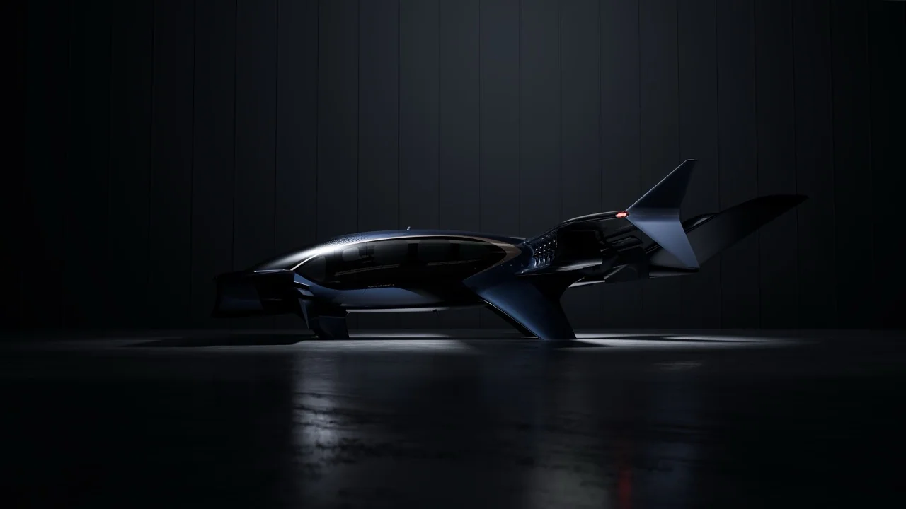
High-Thrust Ducted Fan Sizing Manual (60kgf-1000kgf): Thrust-to-Weight, Voltage & Numerical Case Studies
Step-by-step aerospace sizing guide for electric ducted fans from 60kgf to 1000kgf. Includes VTOL thrust-to-weight bounds, voltage drop, and 2 aircraft cases.
Compatible Airframe Solutions for 60kgf System
Infrastructure & Inspection Powertrains
Enclosed shroud eliminates cable entanglement during standoff inspection with IP55+ industrial ingress seals.
Cruise Efficiency & Mission Range
Breguet electric range modeling with aft tail-pusher BLI reducing cruise drag by 42% to expand corridor mission radius.
Motors, Inverters & Rotor Containment
Eliminate bare motor integration hazards with factory-matched SiC inverters and certified blade containment.
Partners