
Propulsion system sizing dictates gross takeoff weight (MTOW), payload capacity, battery thermal dissipation, and safety margins. Undersizing a powertrain causes dangerous settling in gusty conditions, while oversizing incurs parasitic structural mass. Drawing upon real flight validation across Yuntu’s 60kgf to 1000kgf matrix, this engineering guide establishes sizing criteria and presents two complete numerical derivations.
1. Golden Bounds for VTOL Thrust-to-Weight (T/W) Margins
When calculating VTOL platform requirements, sizing starts with the ratio of total available thrust to Maximum Takeoff Weight (MTOW). Under standard airworthiness certification benchmarks, dual checks are required at Sea Level ISA (15°C, 101.3 kPa) and hot-and-high desert conditions (45°C ambient):
- Nominal Hover Baseline: T/W ≥ 1.25 (reserves 25% thrust delta for rapid attitude control loops).
- Gust & Vertical Climb Margin: Recommended T/W = 1.35 to 1.45 to ensure >2.5 m/s climb rate in Beaufort 6 winds.
- One Engine Inoperative (OEI) Compliance: In distributed multi-thruster architectures, losing 1-2 thrusters must still leave T/W ≥ 1.05 for controlled, fail-safe landing.
2. Numerical Derivations & Sizing Case Studies
Case Study A: 120kg Industrial Survey VTOL Drone
Scenario: Requirement: MTOW = 120kg, vertical takeoff, inspection mission in 40°C ambient heat, cruise speed 120 km/h.
- Step 1 (Model Match): Selecting Yuntu 60kgf units (0.6m diameter, 45kgf rated, 60kgf peak). 40.5kgf operates right in the 90% peak efficiency zone.
- Step 2 (Thrust Authority): 4 x 60kgf units deliver 240kgf peak thrust, yielding an emergency T/W = 2.0 with immense gust control headroom.
- Step 3 (Electrical Bus): 15kW peak rating per unit. At nominal 40.5kgf hover, consumption is 8.5kW each (34kW total hover power). On a 120V bus, total hover current is 283A (70.8A per ESC).
Case Study B: 2200kg 5-Seat Commercial Passenger eVTOL
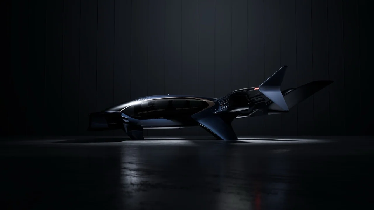
Scenario: Requirement: MTOW = 2200kg, tandem-wing architecture without mechanical tilting, civil aviation 10⁻⁹ safety certification.
- Step 1 (Model Selection): Specifying Yuntu 200kgf thrusters (1.2m diameter, 200kgf peak). Total 20-unit peak output is 4000 kgf. Nominal 150kgf hover operates at 55% throttle.
- Step 2 (OEI Redundancy Check): If 2 units fail in flight (18 remaining), running remaining units at 85% throttle outputs 18 * 170kgf = 3060 kgf, sustaining T/W = 1.39 for safe landing.
- Step 3 (800V High-Voltage Bus): Peak power 50kW per unit. An 800V SiC dual-redundant bus architecture caps peak line current at 625A, eliminating wiring mass.
| Thrust Tier | Outer Diameter | Peak Thrust (kgf) | Peak Power (kW) | Bus Voltage | Target Airframe Class |
|---|---|---|---|---|---|
| 60kgf Industrial EDF Unit | 0.6 m | 60 kgf | 15 kW | 96V - 120V | 40kg - 160kg Industrial inspection & fixed-wing VTOLs |
| 200kgf Aviation EDF Unit | 1.2 m | 200 kgf | 50 kW | 400V - 600V | 200kg - 2500kg Heavy cargo UAVs & distributed eVTOLs |
| 500kgf Heavy-Lift EDF Unit | 1.9 m | 500 kgf | 120 kW | 600V - 800V | 2-4 Seat light passenger air taxis & heavy-lift cranes |
| 1000kgf Megawatt EDF Unit | Custom Cowl | 1000 kgf | 250 kW | 800V+ Liquid | 5-7 Seat transport aircraft & defense logistics platforms |
Frequently Asked Engineering Questions (FAQ)
What is the recommended takeoff thrust-to-weight (T/W) ratio for VTOL aircraft?
We recommend sizing your propulsion matrix for a nominal T/W between 1.35 and 1.45. This ensures the ducted fans operate within their 70%-80% peak efficiency RPM sweet spot while retaining 35%-45% dynamic headroom for attitude stabilization in Beaufort 6 gust conditions.
How much thrust loss occurs under hot-and-high desert conditions?
Thrust scales directly with ambient air density (ρ). In desert climates with 45°C-50°C temperatures and 1,000m altitude, air density decreases by 15%-20% compared to ISA sea level, producing a 15%-22% reduction in static thrust. Sizing must always be validated against these hot-day limits.
What DC bus voltage is recommended for high-thrust distributed electric propulsion (DEP)?
For 60kgf class light airframes, 96V to 120V buses are adequate. For 200kgf to 1000kgf heavy-lift platforms with 10+ distributed units, an 800V silicon carbide (SiC) bus architecture is essential to slash line currents and eliminate excessive cabling mass.
What if standard 60kgf to 1000kgf models do not match my airframe bay or voltage requirements?
Yuntu provides comprehensive bespoke engineering via our [Custom Electric Ducted Fan Engineering Service](/custom-electric-ducted-fan), covering custom aerodynamic cowls, dual-redundant windings, and 800V+ SiC ESC matching. To calculate detailed payload mass fractions and dynamic momentum limits, consult our guide: [Evaluating Industrial Drone Payload Capacity: Momentum Theory & Sizing Guide](/blog/how-much-weight-can-a-drone-carry-propulsion-sizing).