
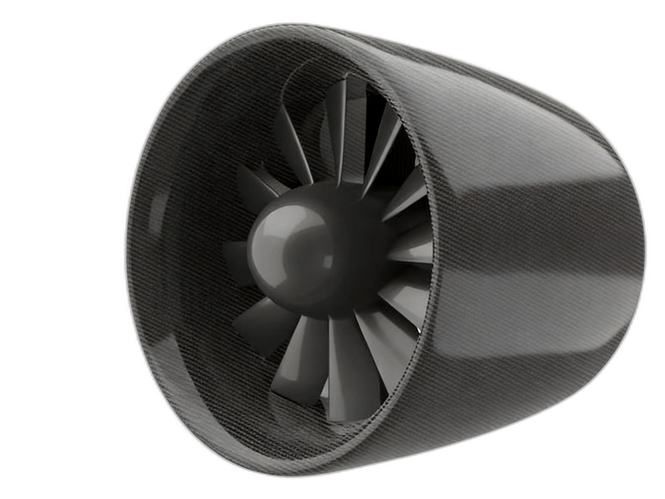
Reference Configuration Specifications
Standard Engineering Envelope & Baseline Performance
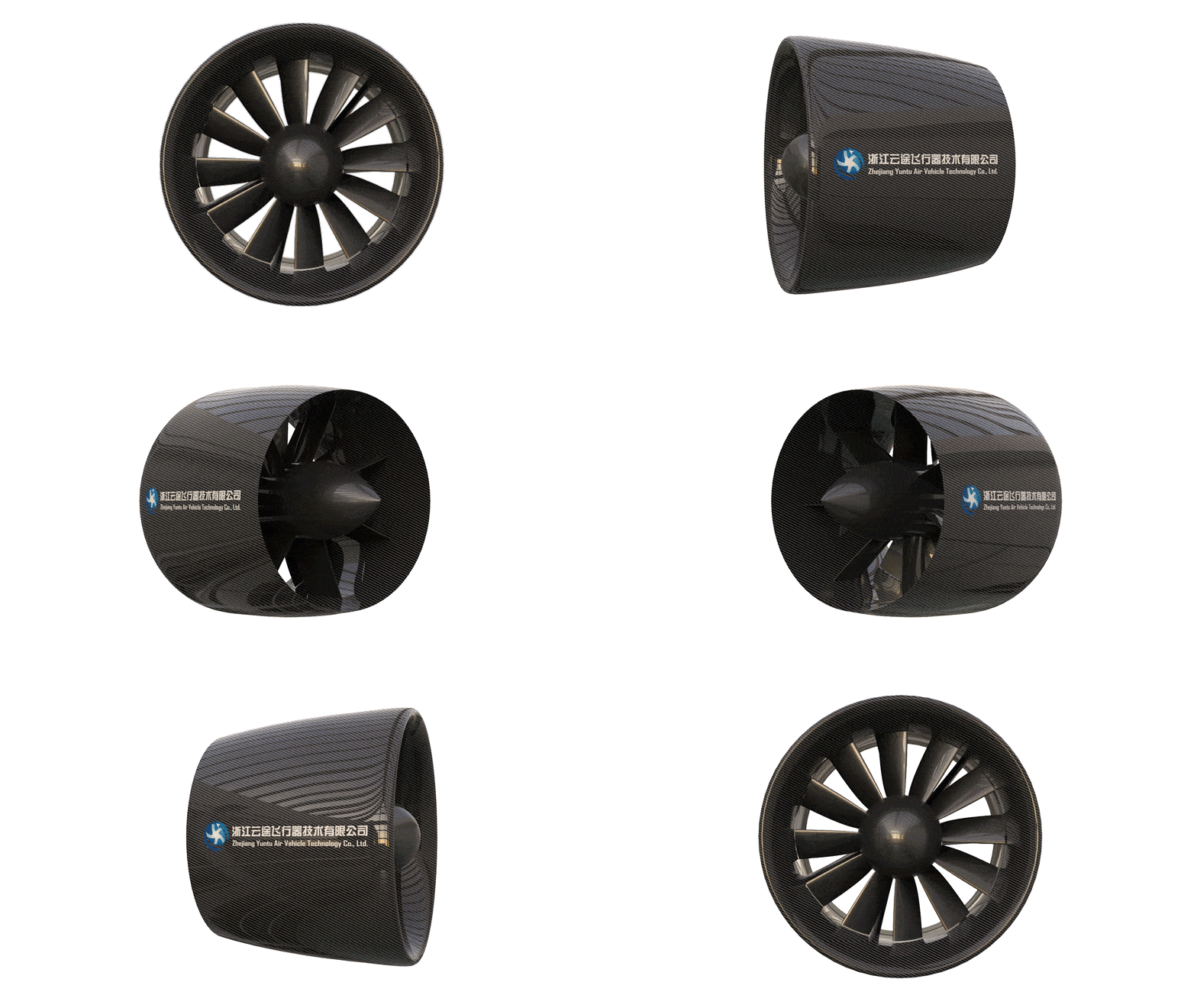 Dynamic 3D Cutaway (9 Blades / 7 Stator Vanes)
Propulsion Engineering Innovations
Eliminates mechanical gearbox failure points while delivering superior acoustic shielding and high aerodynamic cruise efficiency.
600 kW Gearless Direct-Drive Motor
Eliminates the maintenance overhead, lubrication complexity, and single-point mechanical failure risk of planetary gearboxes. Features segmented Halbach array magnets for maximized torque density.
Acoustic Liner & BPF Noise Suppression
Integrated micro-perforated acoustic liner and 7 swept stator vanes cancel blade passage frequencies (BPF), achieving a 12–15 dB reduction in noise signature compared to equal-thrust open propellers.
Autoclave-Cured Carbon Fiber Cowl
High-modulus T800 carbon fiber prepreg shell with diffusion exit geometry. Provides exceptional hoop strength against centrifugal blade containment and minimizes nacelle drag during high-speed cruise.
800V+ Liquid-Cooled SiC Powertrain
Optimized for 800V to 1000V high-voltage DC buses with automotive/aviation-grade Silicon Carbide (SiC) power modules. Internal liquid jacket maintains continuous thermal equilibrium under ISA +30°C hot-day climb profiles.
Target Aircraft Configurations
Proven power allocation models for multi-rotor distributed electric propulsion (DEP) architectures and hybrid-electric commuter aircraft.
5–7 Passenger Vectored-Thrust Air Taxi
Configured in tandem or blown-wing arrangements (6 to 8 units) providing full vertical lift during takeoff/transition and high-efficiency thrust during 260+ km/h forward cruise.
19-Seat Hybrid-Electric Feeder Airliner
Wing-mounted dual or quadruple nacelle installations augmenting wing lift via boundary layer ingestion (BLI) for short takeoff and landing (STOL) operations.
High-Speed Air-Cushion Vehicle & Airboat
Enclosed ducted fan provides personnel protection, zero exposed rotor hazard, and high static thrust resistance against salt spray and coastal sea-spray environments.
Aerospace Engineering Deliverables
Yuntu partners with OEM aircraft design teams, supplying complete aerodynamic, structural, and avionics interface packages.
Full-Scale Wind Tunnel 6-DoF Test Report
Calibrated force-balance data across angles of attack (-10° to +95°) and crosswind conditions up to 45 m/s, validating transitional thrust vectors.
High-Fidelity 3D STEP & Digital Twin Model
Exact mounting flange bolt patterns, Center of Gravity (CG), mass moments of inertia, and finite element analysis (FEA) structural boundary constraints.
Dual-Channel Avionics & CAN/ARINC Bus Protocol
Redundant digital motor controller interface documentation supporting CAN Aerospace, ARINC 429, and RS-485 telemetry feeds with sub-5ms latency.
Comprehensive Propulsion Envelope Map
Multidimensional performance maps mapping voltage, ambient density altitude (0–3000m), inverter temperature, and continuous vs peak torque limits.
Need Full 3D CAD/STEP Models & Avionics Protocols?
Yuntu provides OEM aircraft design teams with mounting flange CAD, mass moment matrices, and CAN/ARINC ICDs.
Frequently Asked Questions
Related Engineering Deep-Dives
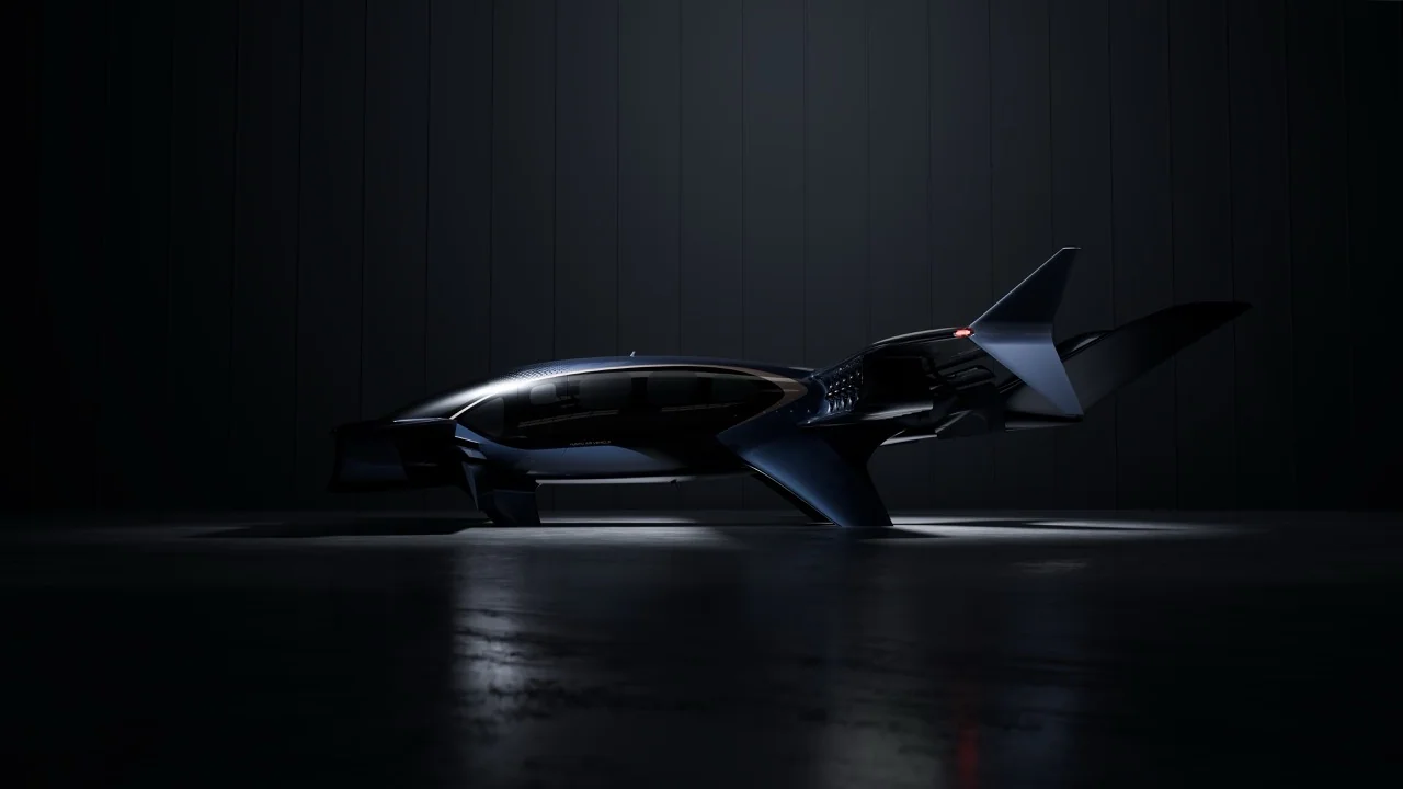 Propulsion Sizing Manual
High-Thrust Ducted Fan Sizing Manual (60kgf-1000kgf): Thrust-to-Weight, Voltage & Numerical Case Studies
Step-by-step aerospace sizing guide for electric ducted fans from 60kgf to 1000kgf. Includes VTOL thrust-to-weight bounds, voltage drop, and 2 aircraft cases.
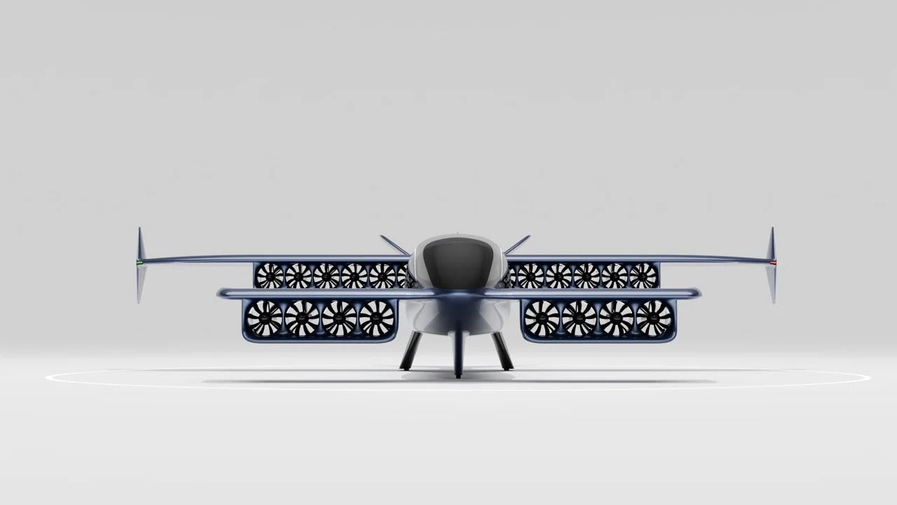 Architecture & Strategy
Distributed Electric Propulsion (DEP) Architecture: Tandem-Wing Aerodynamics & Civil Aviation 10⁻⁹ Safety
Why distributed electric propulsion combined with tandem wings replaces complex tilt-rotor mechanisms and unlocks civil aviation 10⁻⁹ airworthiness safety.
Compatible Airframe Solutions for 1000kgf System
Regional & Passenger Aviation Powertrains
High-thrust electric ducted fan powertrains with 600V–1000V high-voltage bus and full rotor containment safety.
Heavy Lift & Industrial Logistics
Overcoming the open-propeller scaling trap with 20-35% lip suction thrust gain and hot-turnaround cargo safety.
Distributed Multi-Thruster Powertrain
Compact multi-thruster distributed powertrain arrays with 53dB acoustic stealth and OEI safety margins.
Partners