
Aerodynamically Integrated Ducted Propulsion for VTOL & Fixed-Wing Platforms
Engineered for 150 km/h to 250 km/h high-speed cruise regimes. Aft-fuselage Boundary Layer Ingestion (BLI), flush-bay Lift+Cruise isolation, and tilt-duct thrust vectoring for 300km+ commercial surveillance and logistics corridors.
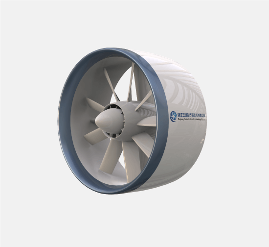
For VTOL and fixed-wing commercial UAVs operating at 150 km/h to 250 km/h, ducted electric propulsion eliminates the severe parasitic drag penalty inherent to conventional open-rotor configurations. In wing-borne forward flight, exposed stopped or windmilling lift rotors create enormous parasitic drag area (CDp · S), degrading vehicle Lift-to-Drag (L/D) ratio by 35% to 50% and slashing battery endurance. Aerodynamically integrated ducted nacelles and aft-fuselage Boundary Layer Ingestion (BLI) recover wake momentum deficits, maintain smooth laminar flow over cowlings, and expand conversion corridor stall margins by 12° during transitional climb.
Mitigating the Stopped-Rotor Parasitic Drag Barrier in Forward Cruise
In high-speed wing-borne flight, total vehicle drag is governed by CD = CD0 + CDp,rotors + CL²/(π e AR). Unshrouded stopped propellers act as bluff bodies in cross-flow, inducing boundary layer separation and collapsing vehicle L/D ratio.
Stopped Rotor Parasitic Drag Elimination
Exposed open propellers locked in cruise create turbulent wake separation at high airspeeds. Flush-bay ducted lift fans or streamlined nacelles enclose stationary impellers, presenting a continuous low-drag aerodynamic profile that maintains boundary layer attachment.
Subsonic Blade Tip Compressibility Management
In high-speed forward flight, open rotor blade tips experience vector addition of forward airspeed and rotational speed, often hitting trans-sonic regimes (M > 0.75) that trigger compressibility drag rise. The ducted diffuser decelerates incoming air prior to blade contact.
Annular Shroud Lift Generation During Transition
During the pitch-over transition corridor (60–120 km/h), the annular carbon fiber duct cowl acts as an auxiliary ring-wing. Its axisymmetric camber generates positive aerodynamic lift at high angles of attack, preventing deep stall.
Safe 3-Stage Flight Envelope Transition Dynamics
Resolving pitch instability, gyroscopic cross-coupling, and wing stall during the critical vertical-to-horizontal conversion corridor.
Stage 1: Pure Duct Thrust Authority
100% of vehicle weight is supported by ducted thrust. Differential RPM and aerodynamic stator guide vanes provide crisp three-axis control with zero gyroscopic cross-coupling moments.
Stage 2: Vector Rotation & Dynamic Lift Transfer
Forward velocity increases as thrust vectors pitch forward or forward pusher throttles engage. Aerodynamic lift smoothly transfers from ducted thrust to wing-borne circulation.
Stage 3: Full Aerodynamic Wing Flight
Main fixed wings carry 100% of aircraft gross weight. Dedicated vertical ducted units are aerodynamically isolated or feathered, while high-velocity pusher ducted pods provide axial cruise thrust.
Re-Energizing Fuselage Wake via Aft-Fuselage Boundary Layer Ingestion
Ingesting decelerated boundary layer air into the tail propulsor maximizes thermodynamic propulsion efficiency while mitigating vehicle form drag.
Wake Momentum Deficit Recovery
As airflow travels along the fuselage, viscous friction creates a thickened, low-velocity boundary layer. The aft tail-cone ducted fan ingests this low-momentum air, accelerating it back to free-stream velocity with significantly less kinetic energy waste than accelerating undisturbed air.
Aft Fuselage Adverse Pressure Gradient Relief
The ducted intake suction at the fuselage tail-cone prevents flow separation across steep boattail angles, eliminating base wake vortices and substantially reducing whole-aircraft form drag.
Axial Exhaust with Zero Swirl Rudder Buffeting
Internal stator de-swirl vanes completely straighten fan exhaust swirl into pure axial thrust, exiting directly behind the empennage with zero asymmetric slipstream buffeting on vertical tail rudders.
Four-Way Quantitative Comparison: VTOL Airframe Propulsive Configurations
Detailed engineering trade-offs comparing Lift+Cruise, tail-pusher BLI, tilt-duct vectored thrust, and traditional open-rotor compound airframes.
Ducted Lift + Cruise (Flush Bay)
Medium-range cargo delivery, offshore oil rig resupply (100–220 km)
Aft Tail-Pusher BLI Fixed-Wing
Long-endurance maritime patrol, border ISR, corridor survey (300+ km)
Tilt-Duct Vectored Thrust Hybrid
High-speed medical emergency transfer, emergency rapid response (220–280 km/h)
Open-Rotor Stopped Compound (Baseline)
Legacy low-speed mapping drones (<130 km/h only)
Full Mission Phase Energy Allocation & The Aerodynamic Leverage Effect
Why reducing cruise drag by 35% yields a 1.6x multiplier on total mission range for commercial VTOL operations.
Vertical Liftoff & Climb (0–90 Seconds)
Ducted lip suction and tip clearance control save up to 14% energy during hover, ensuring battery temperature remains well within safe operational thresholds prior to transition.
Transition Corridor (30–45 Seconds)
Auxiliary annular ring-wing lift allows rapid pitch-over acceleration, reducing transition duration and avoiding high-power stall regimes.
Wing-Borne High-Speed Cruise (60–180 Minutes)
Because cruise accounts for over 80% of total mission energy, eliminating stopped-rotor parasitic drag delivers an exponential range extension (+50% to +75% distance gain).
Vertical Descent & Landing (60 Seconds)
Clean axial ducted wake avoids turbulent ground-effect recirculation, enabling precision sub-meter landing with minimal terminal reserve energy.
Aerospace Ducted Propulsion by Mission Profile
Frequently Asked Questions: VTOL & Fixed-Wing Ducted Propulsion
01How does stopped-rotor drag degrade flight range on conventional VTOL drones?+
02What is Boundary Layer Ingestion (BLI) and how does it save energy on tail pushers?+
03How do ducted propulsors improve safety during the transition corridor?+
04Which architecture is optimal: Lift+Cruise, Tail Pusher BLI, or Tilt-Duct?+
Accelerate Your Fixed-Wing & VTOL Aerodynamic Integration
Share your cruise speed target, wingspan, gross weight, and flight endurance requirements. Our aerodynamics team will perform a 1D drag polar and conversion envelope simulation for your airframe.