
Electric Ducted Fan (EDF) Thrust Calculator & Powertrain Sizing
Compute static thrust, lip suction augmentation, disk loading, and DC bus current based on 1D actuator disk momentum physics and validated wind-tunnel empirical data.
Propulsion Input Controls
ISA ρ=1.225 kg/m³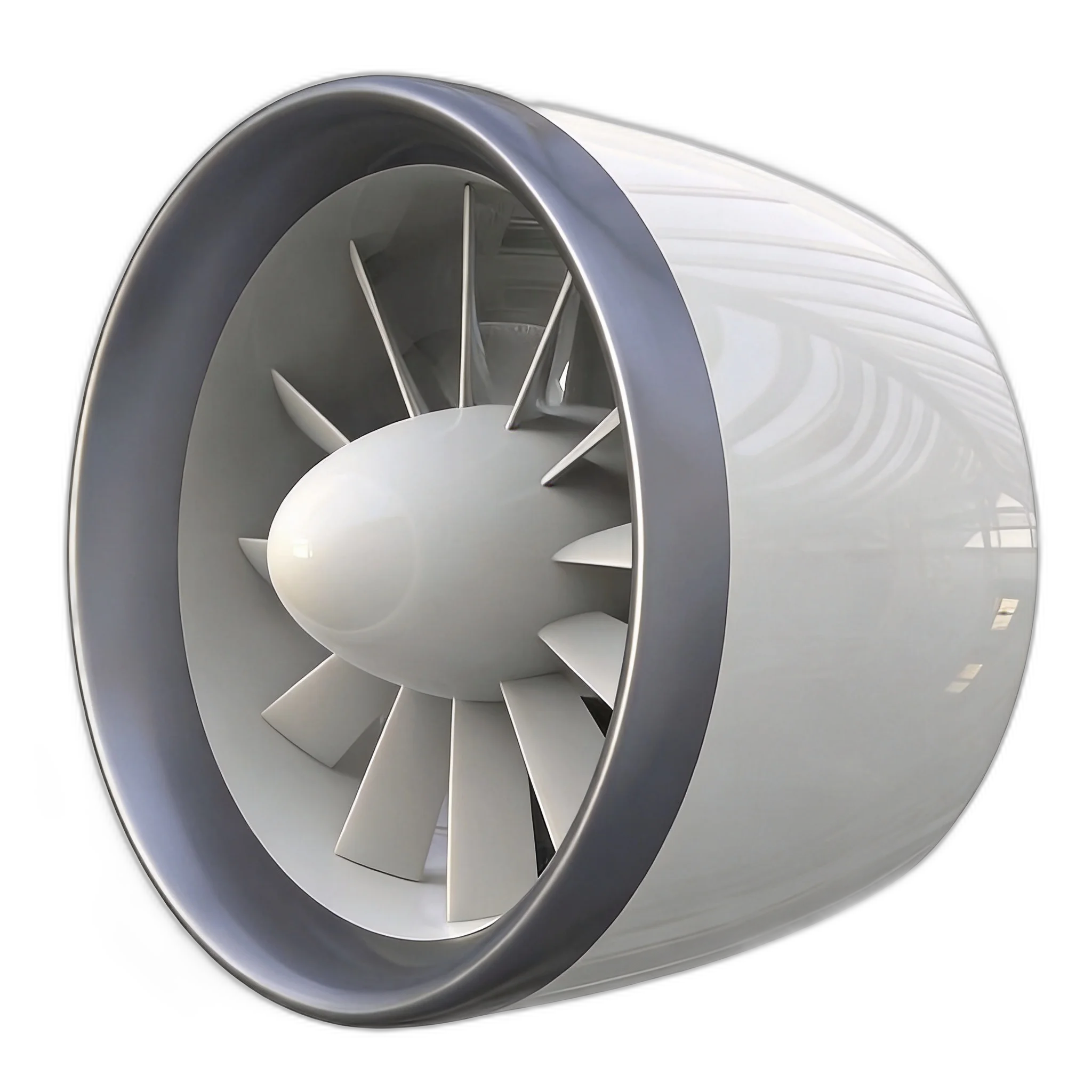
YTF-60 Industrial Heavy-Lift
Standard EDF Thrust & Power Sizing Benchmark Table
Direct reference data for electric ducted fans across standard rotor diameters (250mm to 1900mm) at sea-level standard atmosphere (ISA, ρ = 1.225 kg/m³).
| Diameter (mm) | Power (kW) | DC Bus (V) | Static Thrust (kgf / N) | Exit Velocity (m/s) | Thrust/Power (kgf/kW) | Matched Propulsion Model |
|---|---|---|---|---|---|---|
| 250 mm | 5.5 kW | 96 VDC | 16.5 kgf (162 N) | 52 m/s | 3.00 kgf/kW | YTF-Custom 250 |
| 420 mm | 12 kW | 150 VDC | 34.0 kgf (333 N) | 56 m/s | 2.83 kgf/kW | YTF-Custom 420 |
| 600 mm | 22 kW | 400 VDC | 60.0 kgf (588 N) | 58 m/s | 2.73 kgf/kW | YTF-60 Industrial Ducted Fan |
| 850 mm | 38 kW | 600 VDC | 115.0 kgf (1,128 N) | 62 m/s | 3.03 kgf/kW | YTF-Custom 850 |
| 1200 mm | 50 kW | 600 VDC | 200.0 kgf (1,961 N) | 64 m/s | 4.00 kgf/kW | YTF-200 Aviation Thruster |
| 1900 mm | 120 kW | 800 VDC | 500.0 kgf (4,903 N) | 66 m/s | 4.17 kgf/kW | YTF-500 Heavy-Lift Unit |
| 1600 mm (High PR) | 600 kW | 800 VDC | 1,000 kgf (9,807 N) | 82 m/s | 1.67 kgf/kW | YTF-1000 Megawatt Propulsor |
Aviation Ducted Fan Powertrain Sizing Process
A deterministic four-step engineering procedure for matching electric propulsion to heavy-lift multi-rotors and eVTOL architectures.
Establish MTOW & Thrust-to-Weight Margin (T/W)
Determine all-up gross weight including payload, structure, and batteries. For industrial multi-rotors, target a baseline T/W of 1.4:1 to 1.6:1 for gust margin; for high-altitude or dynamic sling operations, target 1.8:1 to 2.0:1.
Allocate Multi-Rotor Fan Geometry & Disc Area
Divide total thrust by the number of propulsors (quad, hex, or octo configuration). Check vehicle frame envelope limits. Calculate required disk area A = π(D/2)² to ensure disk loading remains below 140 kg/m² for efficient hover.
Incorporate Shroud Lip Suction & Tip Clearance Benefit
Account for duct lip suction T_lip = (0.20 to 0.35) × T_total in static hover. Verify that tip clearance ratio δ/R is under 0.25% (0.8mm–1.2mm) to suppress tip-leakage vortex (TLV) and maintain high Figure of Merit.
Select High-Voltage 400V–800V DC Architecture & Thermal Margin
For units above 20kW, size voltage to keep phase current below 150A. High-voltage 800V SiC architecture reduces wiring harness weight by up to 64% and ensures continuous hover without stator overheating.
Common Engineering Pitfalls in Ducted Fan Sizing
Critical mistakes often made when transitioning from hobby EDFs or open propellers to industrial UAVs.
Mistake 1: Ignoring Duct Shroud Lip Radius
Using a sharp or thin inlet lip causes immediate flow separation at the intake edge during static hover, destroying 25% of potential lift and causing blade stall.
Always ensure an elliptical inlet lip profile with contraction ratio r_lip/D > 0.08 to sustain attached streamline contraction and forward suction.
Mistake 2: Specifying Low Bus Voltage (<100V) on 50kW+ Systems
Attempting to run 50kW at 48V or 96V creates currents exceeding 600A–1,000A, causing prohibitive I²R thermal runaway and massive copper cabling deadweight.
Transition to 400V–800V DC architecture for all propulsors above 20kW to slash conductor weight by up to 64% and maintain cool inverter operation.
Mistake 3: Excessive Blade Tip Clearance
A blade-to-shroud radial gap greater than 1.5% of diameter allows high-pressure exhaust to bleed backward into the suction zone, forming massive tip-leakage vortices.
Use high-rigidity CNC carbon composite duct shells to maintain strict radial clearance below 0.25% (0.8mm–1.2mm).
Fluid Dynamics & Sizing Equations
Actuator Disk Momentum Theory with Shroud Suction Integration
Where ρ is standard air density (1.225 kg/m³), A is rotor disk area π(D/2)², and P is aerodynamic power transferred to the fluid column.
In hover conditions, high streamline contraction over the high-curvature intake cowl induces forward negative static pressure, contributing 20% to 35% of total static lift.
A production ducted fan achieves a Figure of Merit (FM) of 0.74 to 0.78, with inverter and PMSM motor efficiency combined at 90% to 94%.
Tip Clearance Rule: Keep blade radial tip clearance <= 0.8% of diameter to suppress tip-vortex losses and preserve lip suction advantage.
Disk Loading Trade-off: Higher disk loading (>120 kg/m²) increases compact packaging and high-speed efficiency at the cost of hover power consumption.
Thermal Headroom: High-current continuous hover requires ram-air stator cooling to prevent NdFeB permanent magnet demagnetization.
Altitude Density Derating & Forward Speed Transitions
How air density changes with altitude and how cruise velocity shifts aerodynamic power requirements.
| Operating Altitude | Air Density ρ | Static Thrust Derate Factor | Extra Power for Same Thrust |
|---|---|---|---|
| Sea Level (0 m) | 1.225 kg/m³ | 100% (Baseline) | 0% (Nominal) |
| 1,000 m (3,280 ft) | 1.112 kg/m³ | 95.2% | +4.9% |
| 2,000 m (6,560 ft) | 1.007 kg/m³ | 90.5% | +10.3% |
| 3,000 m (9,840 ft) | 0.909 kg/m³ | 85.9% | +16.1% |
| 4,000 m (13,120 ft) | 0.819 kg/m³ | 81.4% | +22.5% |
While open propellers experience severe stall and flutter at high advance ratios, ducted fans benefit from cowl internal diffusion. However, at forward speeds V > 25 m/s, ram drag on the inlet lip and changed blade relative inflow velocity reduce the static shroud augmentation. Transition analysis requires aerodynamic pitch matching or variable pitch blade scheduling.
Related Engineering Guides & Propulsion Solutions
Deepen your powertrain architecture with our published research papers and technical whitepapers.
Heavy-Lift Cargo Drone & Aerial Crane Propulsion Solution
Turnaround-safe ducted fan powertrain arrays for 100kg to 1.2-ton payload platforms.
Global Landscape of the World’s Largest Electric Ducted Fans
Comprehensive analysis of 60kgf to 1000kgf megawatt ducted propulsion systems and eVTOL architectures.
How Much Weight Can an Industrial Drone Carry? Sizing Rules
A complete momentum theory breakdown of payload vs thrust sizing from 10kg to 500kg+.
Industrial UAV Electric Propulsion Sizing & 800V DC Integration
From actuator disk theory to 800V SiC architecture selection for commercial drones.