
eVTOL Safety: Redundancy, Enclosed Rotors and Fault-Tolerant Landing
Eliminating single points of failure across urban skies through 20-fan distributed redundancy, ballistic FAA 33.19 Kevlar blade containment, and powered lift without complex tilting mechanisms.
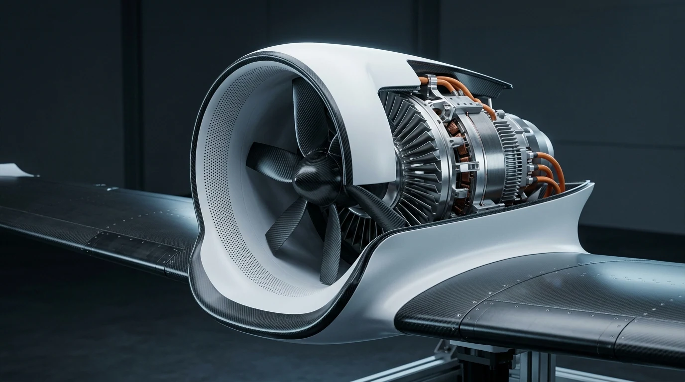
Commercial passenger eVTOL safety is established upon the total elimination of Single Points of Failure (SPOF). Unlike traditional helicopters that rely on a single main transmission gearbox or swashplate, distributed electric propulsion (DEP) utilizes 16 to 20 independent ducted thrusters. If one or more thrusters fail, real-time control allocation algorithms instantaneously redistribute thrust across healthy propulsors, maintaining vehicle pitch, roll, and yaw authority for an orderly, controlled landing.
Why eVTOL Safety Is Fundamentally Different
Traditional rotary-wing aviation concentrates flight-critical loads into single mechanical nodes. Distributed Electric Propulsion replaces mechanical vulnerability with digital multi-channel redundancy.
Elimination of Single Main Transmission
Conventional helicopters feature a central gearbox whose failure is catastrophic within seconds. Distributed electric ducted arrays divide propulsive power across isolated electrical channels with no shared mechanical shafts.
Powered Lift Without Tilting Servos
Tilting-rotor architectures introduce complex mechanical tilt bearings, swashplates, and servo actuators that can jam during transition. Tandem-wing powered lift uses differential fan thrust for vectoring, eliminating critical hinge failure modes.
Segmented Energy & Isolated Power Buses
Propulsion channels operate across galvanically isolated 800V DC power buses fed by physically partitioned battery segments. A single thermal runaway or bus short circuit cannot disable neighboring fan clusters.
The Core Pillars of Ducted Fan Redundancy
How aerospace aerodynamics, mechanical containment, and flight control software combine to safeguard passengers and ground communities.
20 Distributed Ducted Fans: Zero Single Point of Failure
Granular thrust allocation across independent nacelle modulesBy distributing gross takeoff thrust across 20 compact ducted propulsion units, losing a single motor or inverter results in losing less than 5% of total vertical lift. Aerodynamic control margins easily absorb the asymmetry without requiring violent pitch compensation.
Enclosed Rotor Safety & FAA 33.19 Ballistic Containment
Zero open blades in vertiport ground environmentsOpen rotor propellers pose severe decapitation hazards to ground passengers and airport personnel. Yuntu ducted cowls feature Kevlar-reinforced composite containment shrouds engineered to capture released blades or foreign objects during bird-strike events.
Real-Time Dynamic Thrust Re-allocation Control Laws
Instantaneous closed-loop attitude stabilizationTelemetry sensors detect current surges, RPM anomalies, or thermal spikes within milliseconds. The flight control computer automatically shuts down the degraded unit and over-drives diametrically opposed healthy fans, ensuring zero loss of roll or yaw control.
Controlled Landing Scenarios After In-Flight Thruster Failures
Engineering simulations and hardware-in-the-loop (HIL) rig tests demonstrate predictable, controlled flight profiles under severe partial power loss.
| Failure Scenario | Traditional Risk | DEP Mitigation | Control Law Action | Landing Outcome |
|---|---|---|---|---|
| Single Propulsor Failure (One Fan Inoperative - OEI) | Violent yaw snap, immediate emergency autorotation required. | Immediate thrust compensation via opposite fan group; pilot feels negligible yaw. | Slight RPM ramp-up on remaining 19 thrusters (< 4% power reserve). | Normal transition or nominal vertical landing on planned vertipad. |
| Dual Asymmetric Fan Failure (Two Fans on Same Wing) | Uncontrollable rolling moment resulting in catastrophic spin. | Differential elevon deflection combined with inner ducted fan over-torque. | Autonomous rerouting to nearest contingency vertiport or airport runway. | Controlled powered landing with nominal vertical descent rate (< 1.5 m/s). |
| High-Altitude Bird Strike / Foreign Object Ingestion | Exposed propeller shattered, shrapnel punctures passenger fuselage or flight controls. | Composite cowl contains fractured fragments internally (FAA §33.19 compliance). | Damaged motor isolated; flight continues on adjacent independent nacelles. | Safe diversion with airframe and passenger compartment completely intact. |
Safety Targets, Acoustic Compliance, and Public Acceptance
Urban community acceptance is inseparable from aviation safety. A quiet aircraft that operates safely builds the foundation for municipal skyway certification.
Civil Airliner Safety Philosophy (10⁻⁹ Target)
Passenger eVTOL airworthiness regulations establish an allowable probability of catastrophic failure at less than one per billion flight hours (10⁻⁹ / fh). This design philosophy guides every redundancy boundary in Yuntu powertrains.
53 dBA Acoustic Shielding for Urban Skyports
By enclosing the rotor within tuned micro-perforated acoustic liners, ducted fans eliminate blade tip vortex shockwaves. Sideline noise is attenuated to approximately 53 dBA at 100 meters, meeting the strictest urban vertiport zoning ordinances.
Safety & Airworthiness Telemetry
Frequently Asked Questions: eVTOL Safety & Redundancy
Aerospace engineering perspectives on airworthiness, failure tolerance, and passenger protection.
Discuss Safety-Critical Propulsion for Your eVTOL Program
Partner with Yuntu’s aerospace systems engineers to integrate fail-safe distributed ducted fans, FMEA reliability data packages, and acoustic containment nacelles into your airframe.